← back to the build document · §02 mounting · the roof frame · projected dimensions · the parts list · the build manual
The interior frame
The interior does not get a welded aluminum cage bolted around the whole cargo bay, and it does not get Unistrut. It gets two different things that happen to be made of the same metal: light rails that hold wall and ceiling finishes up, and separate, braced, floor-supported modules that carry the bed and the cabinets. Sizing one tube for both jobs is how a build gets heavy without getting stronger — so the sections below are specified by job, six of them, not one. This is a construction method, not a floor plan and not a cut list. Cabinet and bed positions in the drawing are illustrative; every span, quantity and anchor is still open.
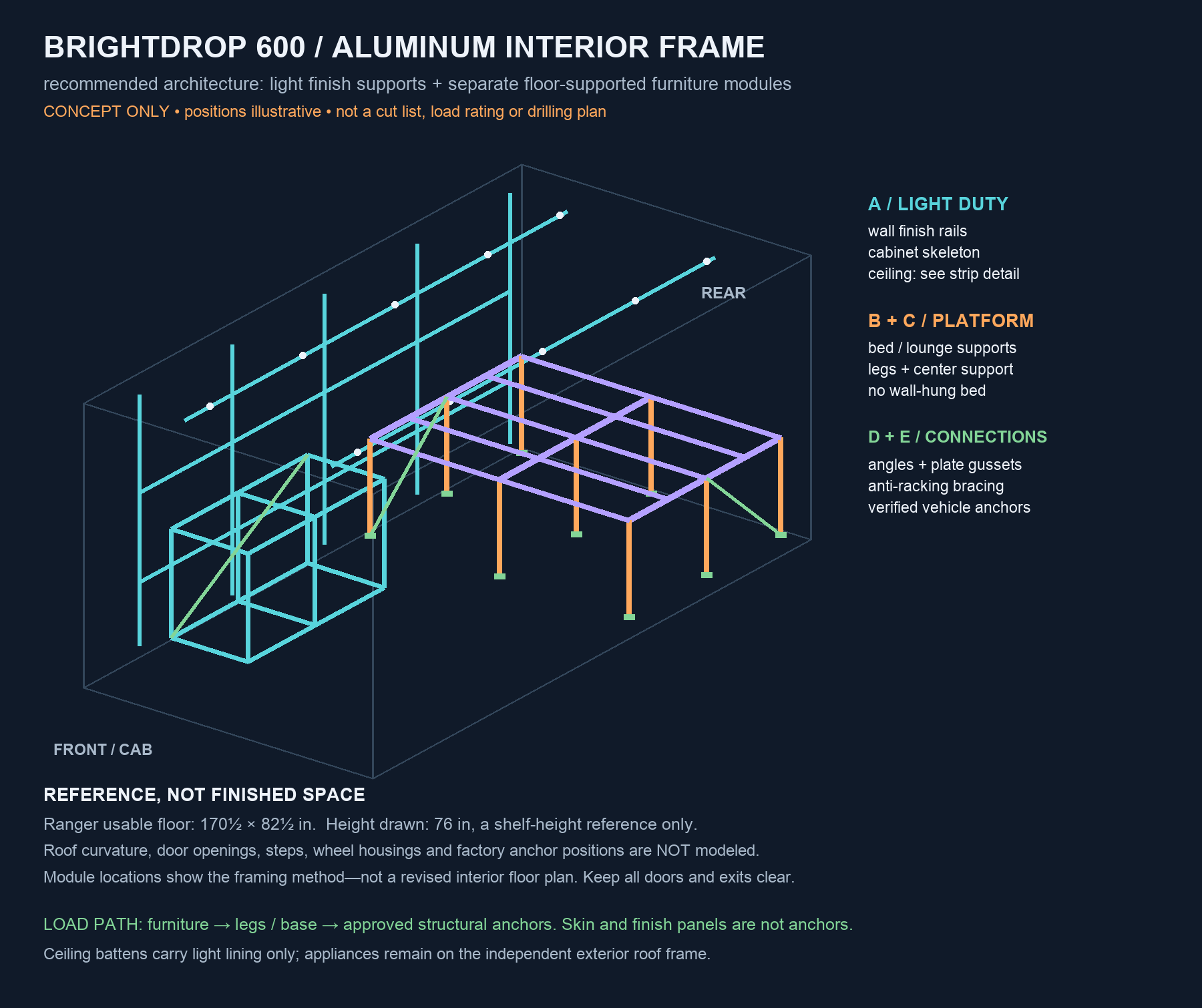
Why modular, and not a cage
The instinct with a big empty box is to frame the whole thing — a continuous aluminum skeleton, wall to wall, floor to ceiling, that everything then hangs off. It is the wrong answer here, for three reasons that all cost either payload or safety:
- Most of a cage does no work. A wall rail whose only job is to hold ¼" birch ply flat needs a fraction of the section a bed beam needs. Running one tube size everywhere means every finish rail is carrying bed-beam weight it will never use. Against a 2,310 lb measured payload, that is the kind of waste that shows up on a scale and never shows up in strength.
- A continuous frame needs continuous anchors. The more the structure is one connected object, the more places it has to be tied to the vehicle — and every one of those attachment points is a hole or a bond in a skin, rib or floor whose substrate, thickness, wiring and HV-pack clearance have not been verified. Fewer, deliberate load paths is fewer things to get wrong.
- Modules can be built and braced on a bench. A bed frame that is structurally complete standing on the shop floor is a bed frame whose strength does not depend on how well it got fastened to a van.
This is the same governing idea §2.2 already states as “build a cassette” — a rigid box of cabinetry that is structurally complete on its own, then tied down. What is new here is the metal to build that cassette out of, and the admission that the finish rails are a different problem from the cassette and deserve a different section.
Which aluminum to ask for
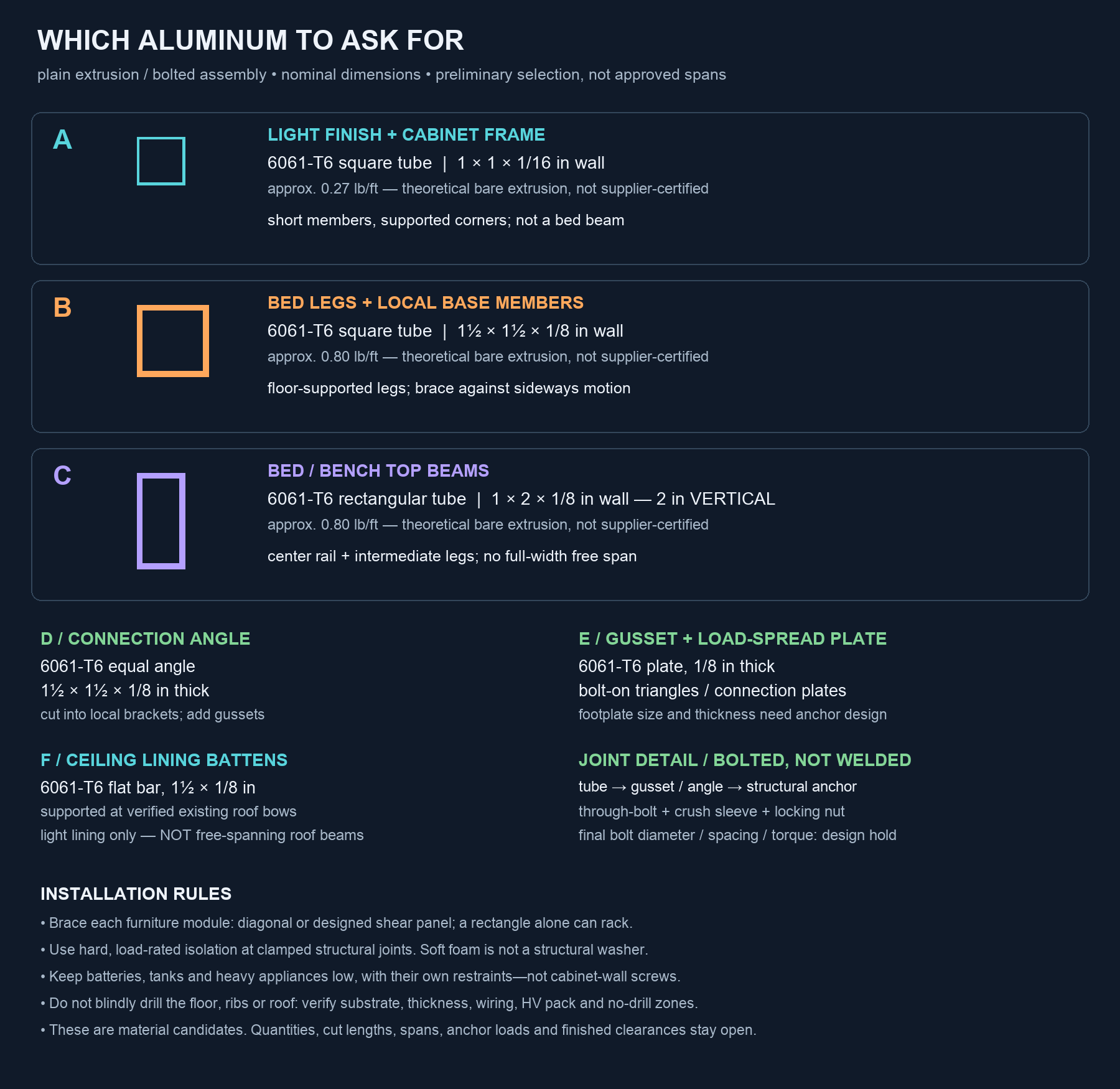
All 6061-T6, all plain extrusion from a stock supplier — no proprietary channel, no T-slot system. Weights are theoretical bare-extrusion figures for comparing options, not supplier-certified.
| Job | Section | ≈ lb/ft | The limit on it | |
|---|---|---|---|---|
| A | Light finish supports + cabinet skeleton | 1" × 1" square tube, 1/16" wall | 0.27 | Short members with supported corners. Not a bed beam, not an anchor for a heavy appliance. |
| B | Bed legs + local base members | 1½" × 1½" square tube, 1/8" wall | 0.80 | Floor-supported. Must be braced against sideways motion and restrained to verified vehicle structure. |
| C | Bed / bench top beams | 1" × 2" rectangular tube, 1/8" wall — 2" vertical | 0.80 | Center rail plus intermediate legs. No full-width free span. Stationary sleeping and lounging only — not a travel seat, not seat-belt structure. |
| D | Connection angle | 1½" × 1½" equal angle, 1/8" | — | Cut into local brackets; add gussets where rotation matters. |
| E | Gussets + load-spread plate | plate, 1/8" thick | — | Bolt-on triangles and footplates. Triangle size, bolt pattern and footplate thickness all need separate anchor design. |
| F | Ceiling lining battens | 1½" flat bar, 1/8" thick | — | Supported locally off verified existing roof bows. Light lining only — these are not free-spanning roof beams. |
How it bolts together
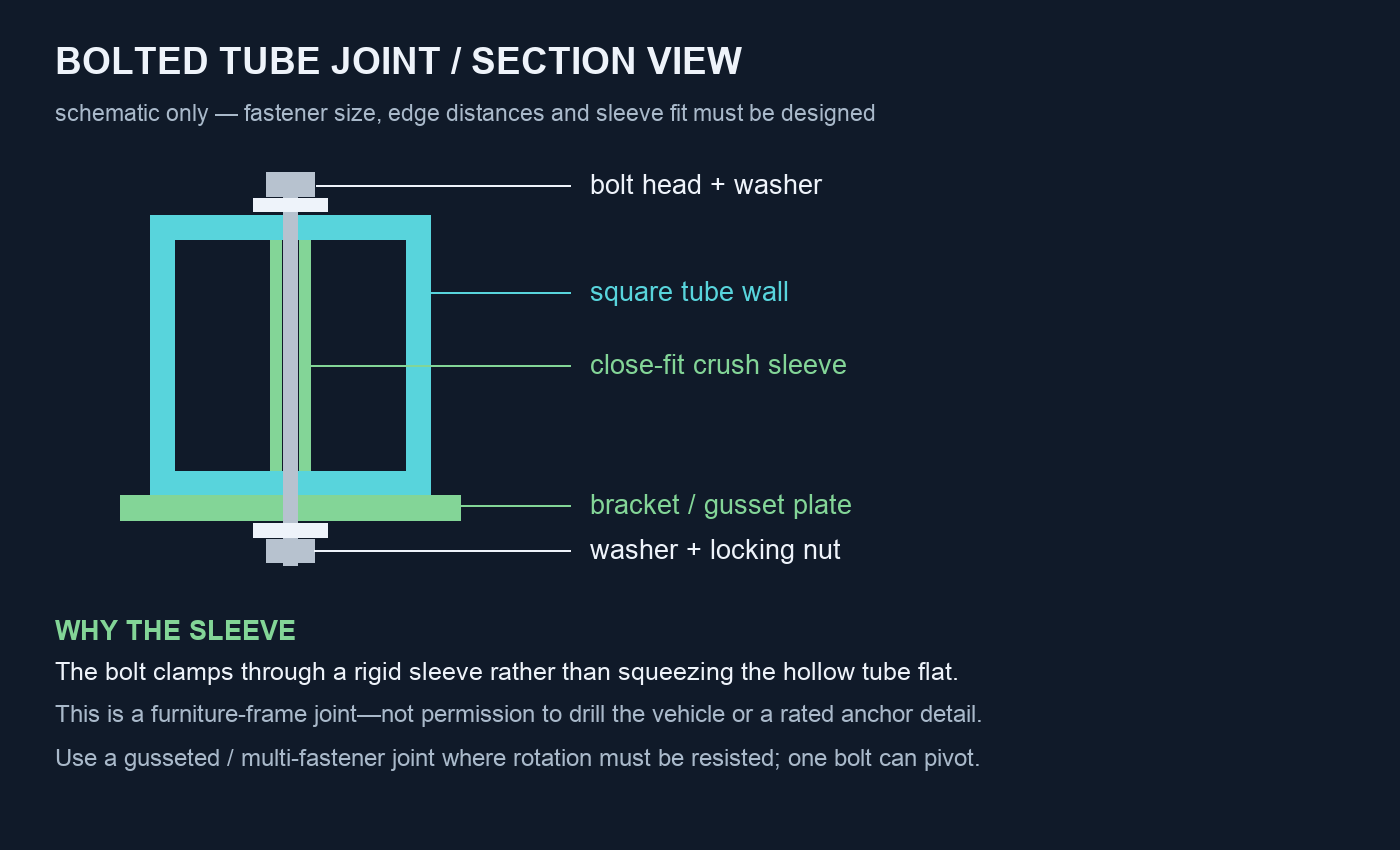
Modules are bolted, not welded — using angles for the local brackets and plate gussets wherever a joint has to resist rotation. Welding 6061 is possible and would look tidier, but a bolted assembly can be built in pieces, carried into the van through a door opening, adjusted when a measurement turns out wrong, and taken apart again. It also avoids putting heat into a heat-treated alloy in a shop that has no way to re-temper it.
The crush sleeve is the part people skip
A bolt tightened straight through a hollow tube squeezes the tube flat. The joint then feels tight, loses preload as the walls deform, and works loose on a road that never stops vibrating. A rigid, close-fitting sleeve inside the tube gives the bolt something incompressible to clamp against, so tightening produces preload instead of damage.
Installation rules
- Brace every module. A rectangle of tube with pinned corners is a parallelogram waiting to happen. Each module gets a diagonal or a properly designed shear panel — the cabinet back can do this job, but only if it is specified and fastened as a shear panel rather than as trim.
- Isolation tape is not a structural washer. Soft foam or rubber at a finish rail stops rattles and is worth using there. At a loaded joint, a compressible layer under the clamp bleeds off preload over time. Loaded joints get hard, load-rated isolation and designed fasteners.
- Heavy things go low and get their own restraints. Batteries, water tanks and heavy appliances are restrained to structure directly — never carried on cabinet-wall screws, and never relying on the cabinet they happen to sit inside.
- Do not blindly drill. Not the floor, not the ribs, not the roof. Substrate, thickness, wiring routes, HV-pack clearance and no-drill zones all get verified before a hole exists. Rivnuts into “a rib” is an assumption about what that rib is made of and what is behind it.
- Keep every door and exit clear. The drawing does not model the door openings, so it cannot warn you when a module lands in one.
What this does not establish
Everything below is open, and none of it is unblocked by the Ranger guide.
- Any span. No member length on the drawing has been checked against a deflection or strength limit. The intermediate supports are drawn because unsupported full-width spans are a known bad idea, not because a span was calculated and found to need one there.
- Any anchor. Footplate size, plate thickness, bolt pattern, fastener grade, edge distance and torque are all design holds. So is what the fastener lands in — no attachment point in this van has been verified for substrate or clearance.
- Any quantity. Cut lengths and piece counts follow the final layout and the support spacing, and neither is locked.
- The positions in the drawing. Cabinet and bed locations illustrate the method. They are not a revision of §03.
- Anything about the physical box. The envelope drawn is Ranger's usable floor figure, and its 76" is a maximum-suitable-shelf-height reference, not a ceiling. Roof curvature, the cab step, the wheel housings and the real door openings are not in the model. The tape measure decides all of it.
Status: a recommended construction method and a preliminary material selection — the thing to walk into a metal supplier with, and the thing to check a layout against. Not an engineered design, not a cut list, and not a drilling plan.