← back to the build document · building the roof rack · the build order · the standard brackets · the rack for the lengthwise layout · the roof frame · the interior frame · building the a/c & fan frames · the parts list
Mounting the A/C and the fan
Jack's question killed a design: if the appliance has to be cut into the roof and sealed to the roof, why is it sitting up on the solar rack? It shouldn't be. The appliances seal at roof level, an internal frame under the roof carries them, and the solar rack is a separate structure that stays clear of them. It starts with the factory structure the frame attaches to — GM's own body-structure figure, not a concept — then four drawings, the assembled section first, because that is the one that answers the sealing question. Drawn by Mickey. Concept geometry only: no member sections, no spans, no hole patterns, no fastener specs.
What changed, and what it replaces
The earlier concept raised the A/C and the fan to rack height. That looked tidy in a drawing, and it quietly created the hardest unsolved problem on the roof: a tall, structural, weather-sealed passage bridging the gap from the roof opening up to a raised appliance, on a unit whose manual never approved that mounting height in the first place.
"Don't rely on unsupported roof sheet" was never the same statement as "everything must sit on the exterior rack." The roof sheet needs support underneath it; it does not need the appliance lifted away from it. Those are two different fixes, and the second one costs a lot more than it buys.
The revised architecture, in one line each
- Exterior solar rack. Carries solar. Crossbars get arranged around the A/C and the fan so they never obstruct airflow, the fan's lid travel, or service access. It no longer carries any appliance load.
- The appliances. Sit at their roof openings, at roof level, sealed by their own factory gasket / flange systems, exactly like a normal roof install.
- Interior reinforcement frame. A new, separate frame under the roof. Carries appliance weight, clamp reactions and screw engagement into verified vehicle structure.
- The roof sheet. Participates locally in a supported sandwich and passes compression through. It is never asked to span and carry an appliance on its own.
The structure this actually attaches to
not a concept drawing — GM's own body-structure figure, 25MY Chevrolet BrightDrop 400/600 Body Builder Manual, page 9
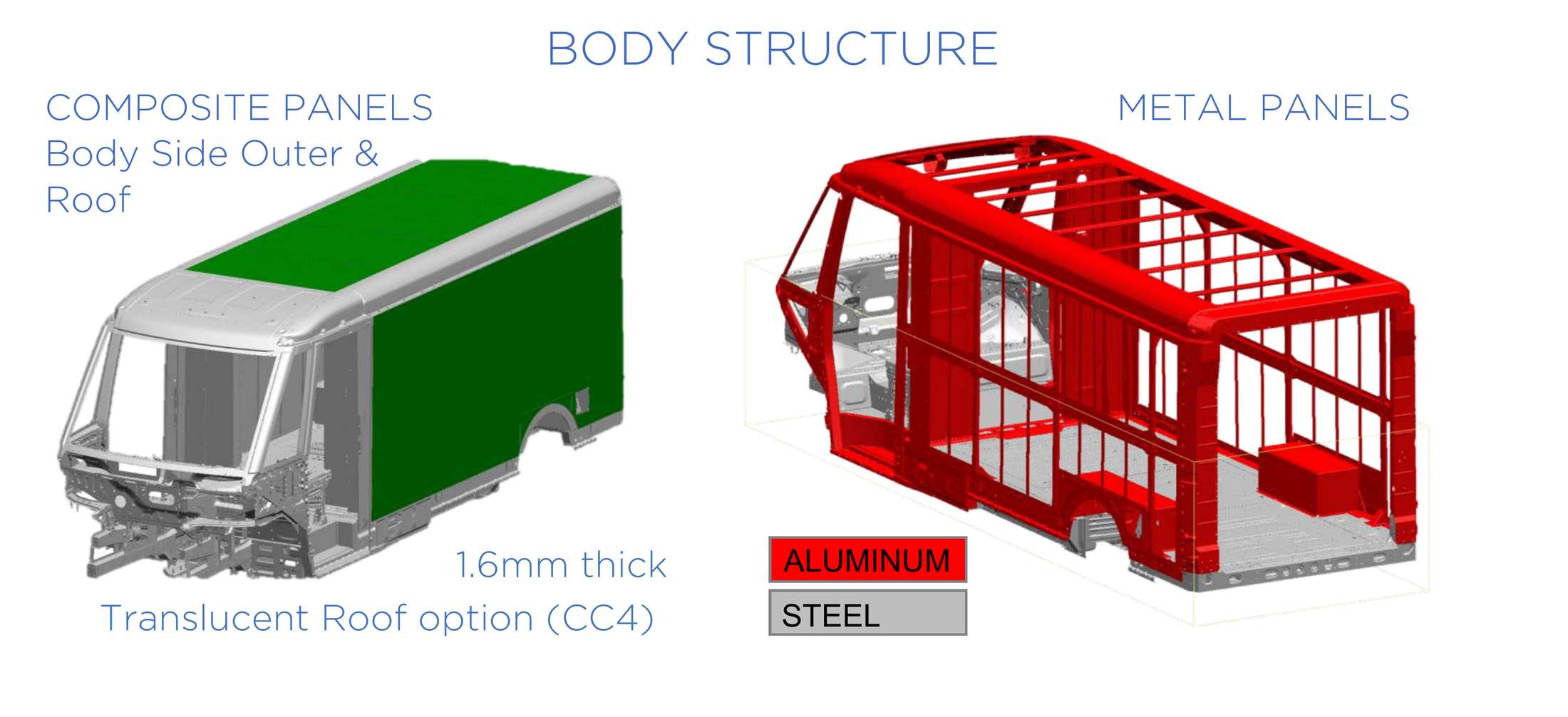
Every earlier version of the drawings below ran the load out to pink members captioned "symbolic — not actual BrightDrop factory rails." That caveat existed because we had no documented structure to draw. We do now. Sheets 01 and 02 have been redrawn against this cage and no longer contain invented endpoints; sheets 03 and 04 are unchanged and still carry the old symbolic pink. What the documented cage changes is four things.
- The roof skin is not structure, and that is now sourced rather than assumed. A 1.6 mm composite panel is a weather enclosure. The argument for an internal frame no longer rests on a general claim about "thin roof sheet" — it rests on the manufacturer's own material callout.
- There is a candidate load path, and it is short. Appliance → cradle → roof bows → cant rails → side posts → lower body and floor structure. The frame is no longer hunting for somewhere to land; the landing points are factory members that already carry the roof. But the number of bows is not settled. Sheets 01 and 02 draw the cradle spanning two adjacent bows to make the path legible — two bows are not proven sufficient, and the A/C's actual footprint and loads may require a wider span, more bows, or a different support arrangement entirely.
- The roof-rail airbag envelope is documented, which is not the same as clearance. The roof-rail airbags are 1800 mm wide and 1087 mm tall and are shown in the cab (manual p35). That figure is a deployment envelope drawing — it is not permission to ignore wiring, harnesses or VIN-specific variation anywhere else in the vehicle, and it does not certify any particular cant-rail station as clear. Forward of the bulkhead the caveat plainly stands; aft of it, clearance is still something to establish on the actual van, not read off a figure.
- The published no-drill / no-cut zones do not name the cargo roof — and that is not the same as clearing it. Manual p30 calls out no drilling above the HV battery, no cutting orange HV cable, no modification of HVAC plumbing, and cab SRS / airbag hazards. They are not all underbody. An area left unshaded on p30 is not an authorisation to drill it — the page marks known hazards, it does not issue permission. Drilling or through-bolting any factory member on this vehicle remains unapproved until GM documentation or a qualified inspection says otherwise.
1 · Start here: the assembled section
this is the drawing that answers "how does it seal if there's a frame in the way"
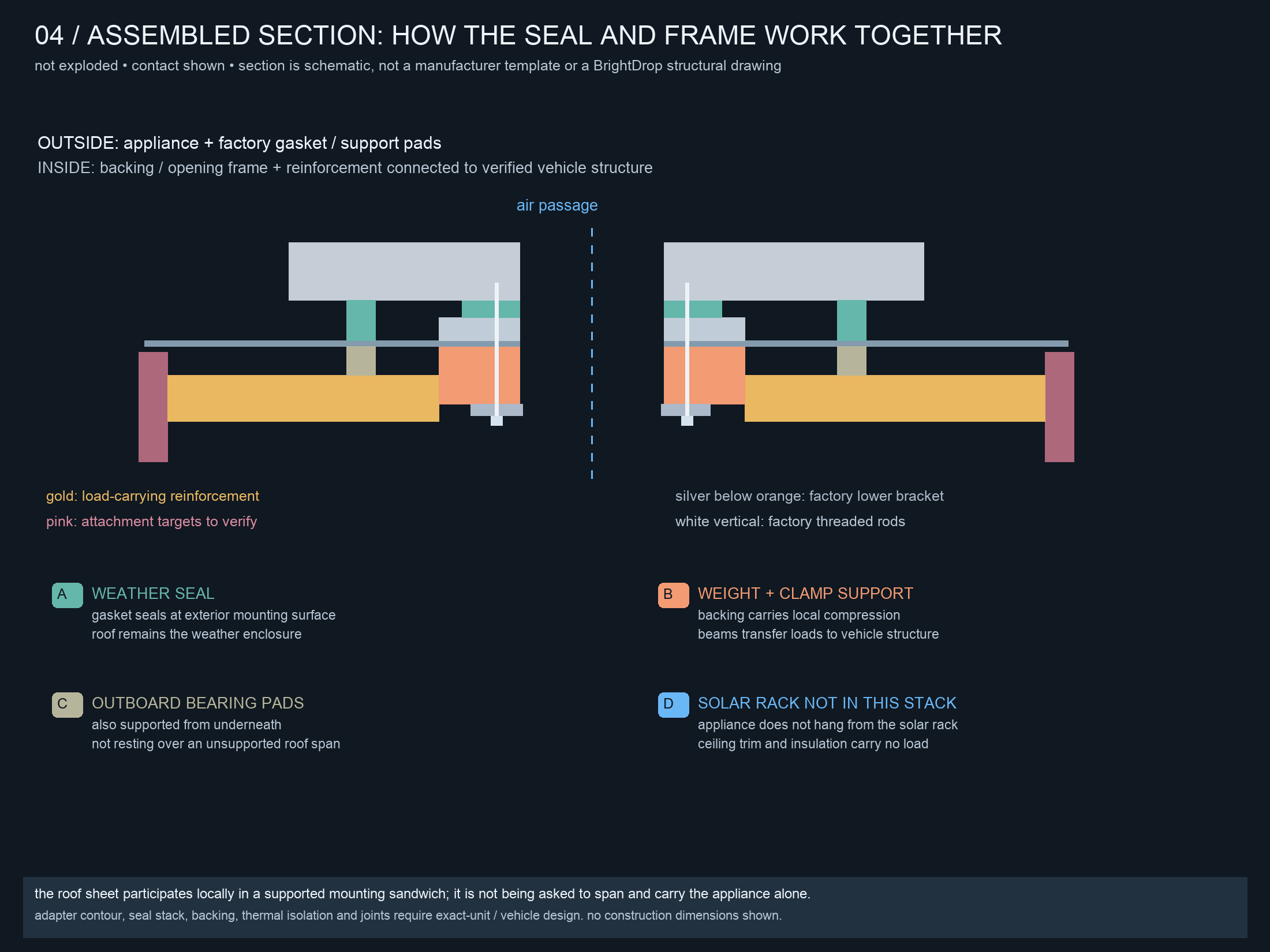
Read top to bottom that is one continuous compressed stack. There is no gap, no riser and no tall throat anywhere in it. That is the entire point of the revision.
2 · Where the internal frame actually sits
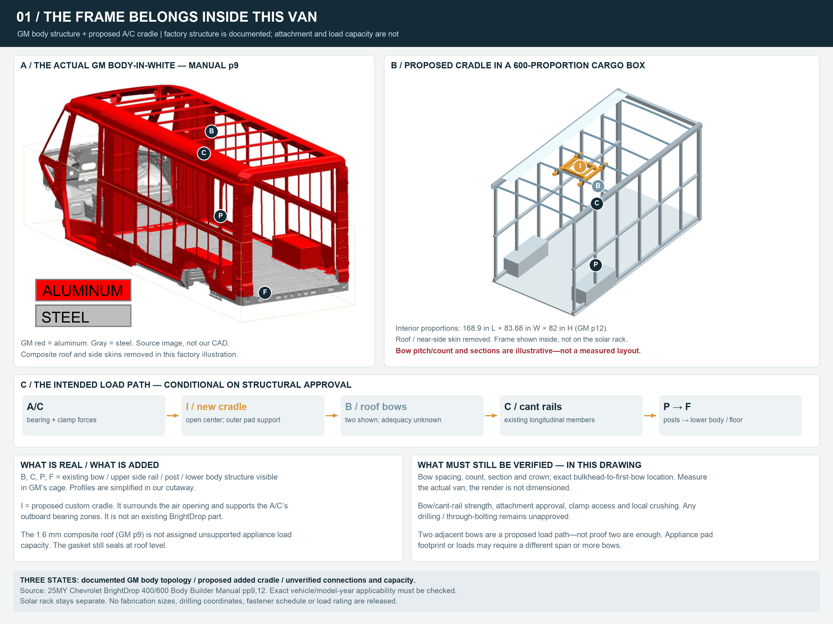
The load path, written out
appliance → its own supported mounting surfaces → structural backing → internal frame → verified vehicle structure.
Not appliance → unsupported roof panel. Not appliance → ceiling lining or trim. And not appliance → solar rack, which is the path the old drawing implied.
The cradle drawn here exists to make the load path legible. Its span, section and the two-bow arrangement are illustrative — not proof that this geometry is necessary, and not proof it is sufficient. The fan in particular may need much less structure than the A/C if suitable vehicle structure is verified nearby.
3 · The A/C: clamped through a supported sandwich
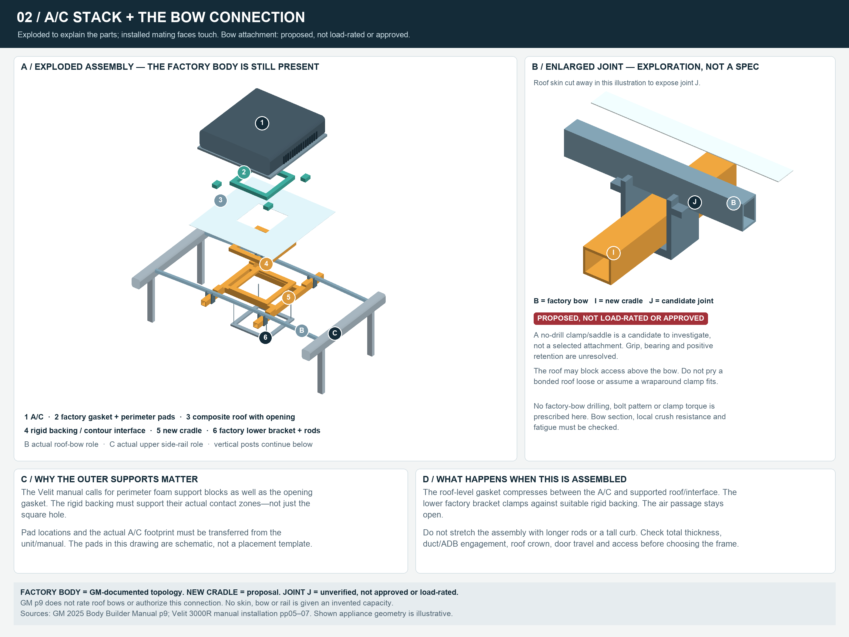
The correction the square-frame idea misses
A ring around the opening is not enough. The A/C's own manual calls for perimeter support blocks outboard of the opening, and those blocks need structural bearing beneath them too. A frame that supports only the hole leaves the unit's outer bearing points sitting over unsupported roof panel — which is the exact failure the whole design is meant to avoid. Extend the members, or add supported landings where the real unit needs them.
4 · The fan: a screw flange, not a clamp bracket
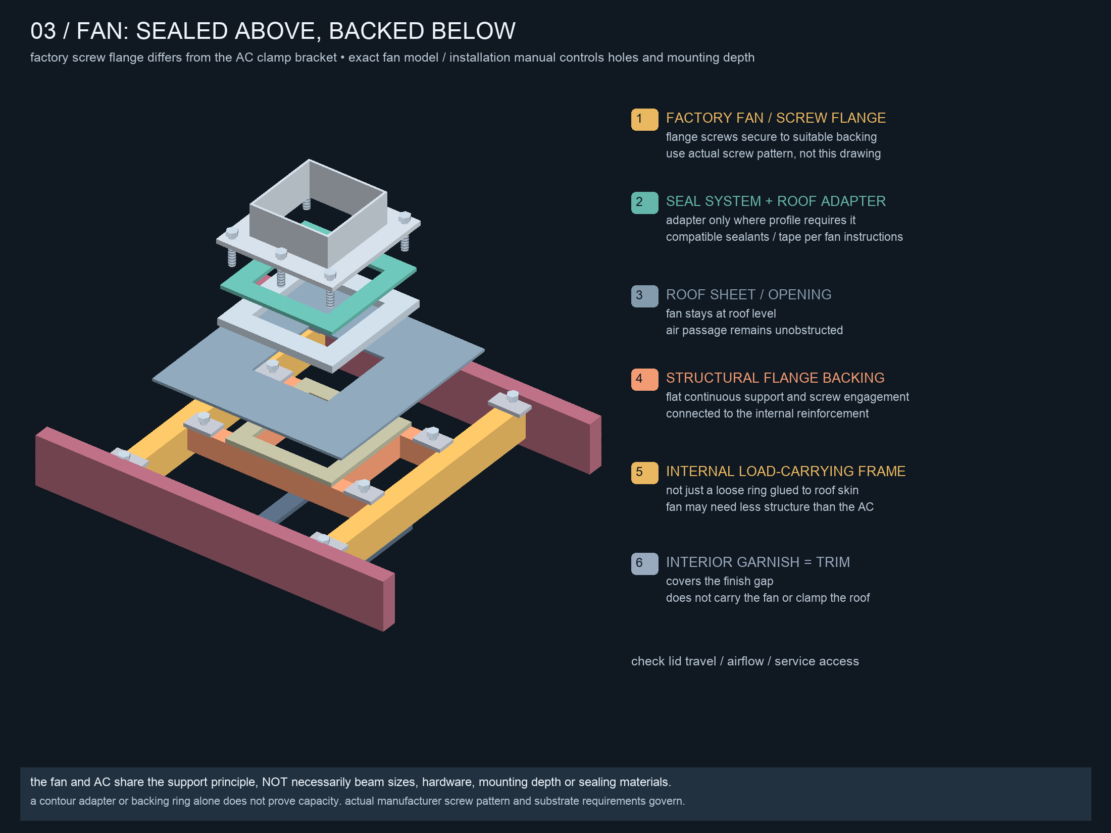
Sharing a principle is not sharing a specification. The fan and the A/C agree on seal above, support below — they do not necessarily agree on beam sizes, hardware, mounting depth or sealing materials.
The part key
identification for design and quoting — nothing here is a selected section
| ID | Part | Role | Status |
|---|---|---|---|
| S | Exterior solar rack | separate | Carries solar only. Appliance load is removed from its job in this concept — but the rack itself is still not an approved design. See the rack build page. |
| I1 | Internal transverse beams | cut | Bridge to verified vehicle structure; carry the opening frame and the outboard A/C bearing pads. Closed structural tube concept — section, count, span and anchors all unselected. |
| I2 | Trimmers and headers around the opening | fabricate | Keep the air passage clear while carrying the mounting interface into I1. Custom tube / angle frame; every connection still needs design. |
| I3 | Continuous backing and bearing surfaces | fabricate | Support gasket and flange compression, clamp reactions, screw engagement and the perimeter pads. Appliance- and roof-specific. Not a decorative adapter. |
| I4 | Vehicle attachment brackets and targets | fabricate | Transfer load into verified body structure. The pink members that remain in sheets 03 and 04 are symbolic targets — not verified BrightDrop rails, not approved locations, no capacity established. Sheets 01 and 02 now land on documented factory bow, cant-rail and post roles instead, but the connection to them is still proposed, not load-rated and not approved. |
| OEM | Factory flange / bracket, rods, screws and seals | supplied | Attach and seal per the exact appliance manual. Do not substitute generic hardware and do not apply rack torque values. |
| J | Frame joints and connection hardware | buy + cut | Positive structural connections, named retention, crush protection where a bolt clamps hollow wall. Engineered per substrate — not a universal rivnut prescription. |
Candidate stock families — not chosen sections
- I1 / I2 tube: 6061 rectangular tube →
- I2 angle: 6061 angle →
- I3 / I4 plate: 6061 plate →
What the manufacturer documents actually say
retrieved and read, not remembered
Vehicle — 25MY Chevrolet BrightDrop 400/600 Body Builder Manual
GM's upfitter manual for the platform, read directly rather than summarised. Page 9 gives the body structure: body side outer and roof are composite, 1.6 mm thick, over an aluminium cage of cant rails, transverse roof bows and side posts — the figure is at the top of this page. Page 30 flags the 600's no-drill / no-cut hazards — above the HV battery, orange HV cable, HVAC plumbing and cab SRS; they are not all underbody, and an area it leaves unmarked is not an area it authorises. Page 35 gives the roof-rail airbag deployment envelope, 1800 mm × 1087 mm, in the cab — a hazard drawing, not a clearance certificate for wiring elsewhere. Page 9 also rates the eight fixed floor tie-downs at 1,000 lb each.
A/C — Velit 3000R
The planning direction from the main document is the Velit 3000R. Its manual was retrieved from the manufacturer link and read. Four things in it matter here:
- The opening is 14¼" × 14¼", not "14 × 14". The marketing shorthand and the manual disagree. Cut to the supplied unit's manual and template, never the shorthand.
- Also specified for the existing-opening case: slope below 15°, and 3" of interior trim clearance around the opening edges. That is an interior-fit constraint — not a statement about exterior condenser clearance.
- Gasket over the opening plus perimeter support foam blocks. This is the line that forces the reinforcement to reach outboard of the opening ring.
- Four M8 rods, factory lower mounting bracket, washers, anti-slip nuts, with a 4.5–5.6 Nm instruction for that clamp assembly. That is not the reinforcement or rack bolt torque and must never be borrowed as one.
Fan — MaxxFan Deluxe family
Product family: maxxair.com →. Prior project discussion used the 7500K. Nothing about the opening, screw pattern, pilot holes, backing material, sealants or mounting-thickness range is settled until the actually-selected model's installation manual is in hand.
How it gets built — bench first, roof last
- Map the appliance underside. Opening, gasket line, support pad positions, screw holes or clamp reactions, and the interior trim footprint.
- Establish where the reinforcement can legitimately attach. Vehicle documentation or qualified inspection — not a tape measure, not a photograph.
- Mock up the full mounting height with the real duct, air-distribution box or fan mounting thickness before anything is cut.
- Only once sections and joints are resolved: cut, deburr, assemble on the bench, check both diagonals for square and the mounting surface for flat.
- Fit the backing and every required perimeter bearing landing.
- Install the frame in the van with its specified connections, sleeves and retention.
- Dry-fit the appliance before cutting the roof. Every bearing point, clamp and screw access, airflow, fan opening envelope, drainage and service access.
- Only after that fit is accepted: create the roof opening and the weather connection, install per the appliance's own spec, leak-test, inspect.
Where this lands against the rack work — and which of it is gated behind the measurement pass — is the rack build order. Note the rack's supports are now catalog strut fittings, while this internal frame is still a fabricated structure with an unverified joint to the factory roof bows. Do not cut structural ribs to make the illustrated opening fit.
What this settles, and what it does not
Status: a revised concept and the preferred direction to investigate. Not a released structural design, not a cut list, not an approval to open the roof. Those need vehicle documentation or qualified inspection, plus a completed design — the same gate as the rest of the roof work.
All four sheets are in the printable version: the appliance mounting concept (PDF) →