← back to the build document · why the frame exists · the rack for the lengthwise layout · every rack part, pictured · what the van gives you · what the appliances demand · the design · what to buy · the build, step by step · the parts list
Building the A/C and fan frames
A first metal build, written for someone who has not done one. Nothing here is welded, bent or machined. Each frame is a flat rectangle of the same 1⅝ in aluminium strut the roof rack uses, bolted at the corners with catalog plates, hung under the roof skin from two factory roof bows, with a strip of flat bar on top for the appliance to clamp against. The tools are a saw, a drill, a tape and a socket set. The appliance page explains why the frame exists; this page is how to make it.
1 · What the van gives you — from the GM upfitter manual
25MY Chevrolet BrightDrop 400/600 Body Builder Manual, read directly · pages 2, 9 and 30
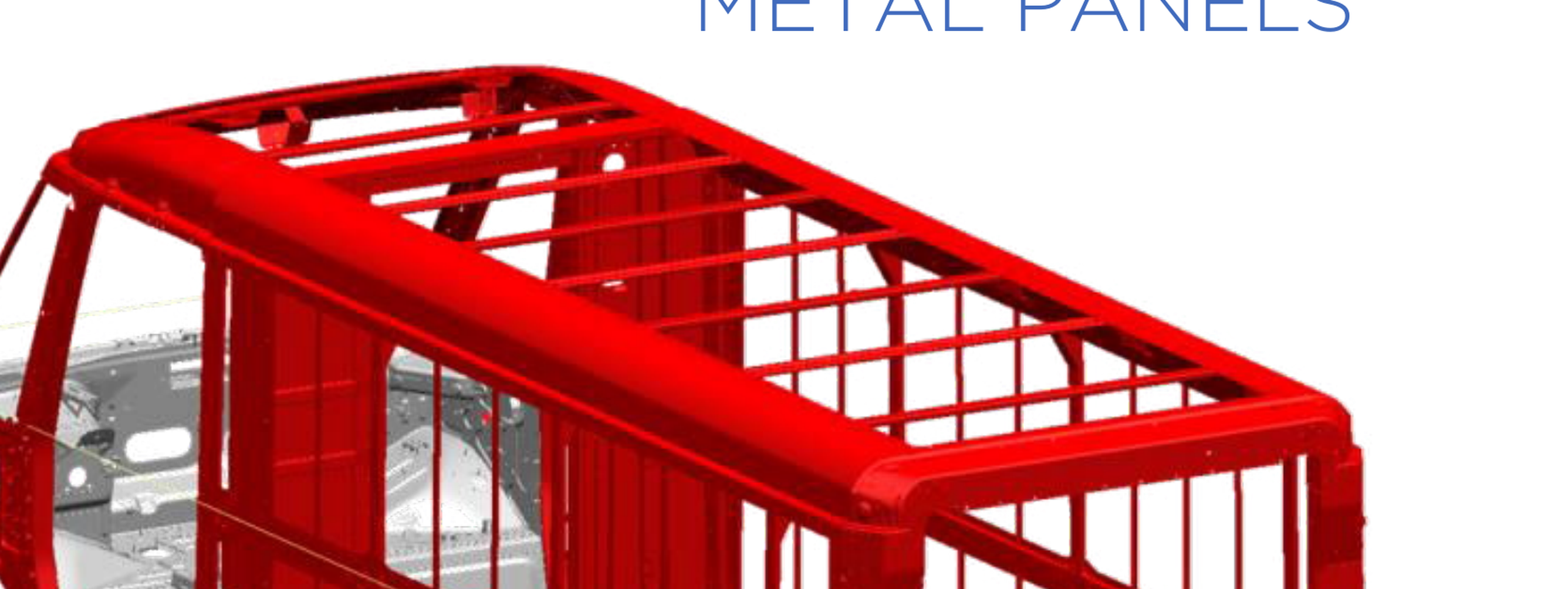
- What it says. Roof and body-side outer panels: composite, 1.6 mm. Cage: aluminium. Cargo floor: composite sandwich with an 8 mm mat, eight tie-downs rated 1,000 lb each (page 9). Every hole drilled in the body must be corrosion-protected and properly sealed (page 2).
- What it does not say. Bow count, bow pitch, bow section, whether a bow may be drilled, and what any roof member can carry. The rendering shows what look like nine or ten transverse bows over the cargo box and a pair of thin fore-aft stringers between them — read off a picture, so it is a hint for what to expect under the tape, not a dimension.
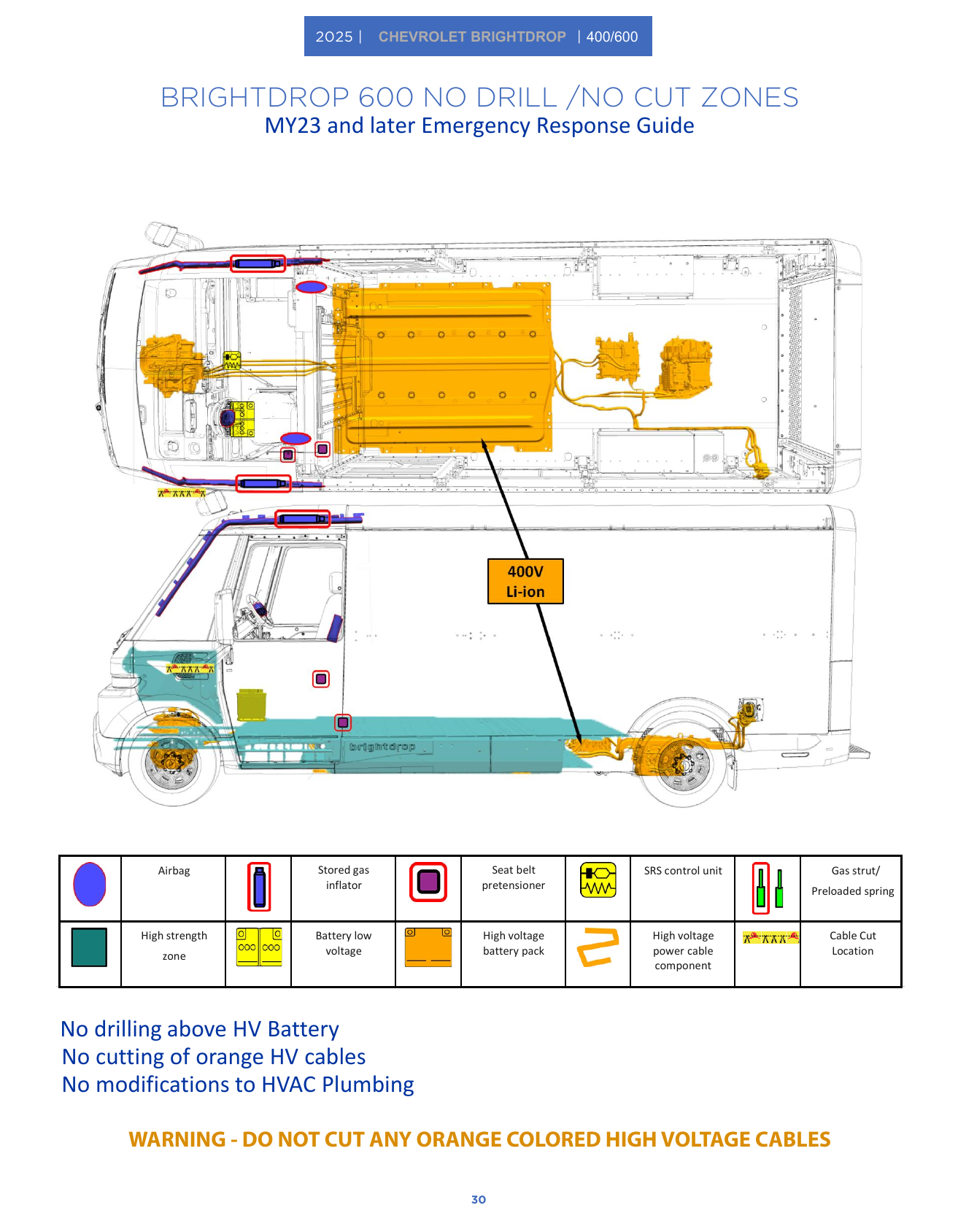
- No-drill / no-cut zones (page 30). No drilling above the high-voltage battery (the floor, between the axles), no cutting orange HV cables, no changes to HVAC plumbing, and the airbag deployment zones — the roof-rail airbags run along the cab roof edges above the doors. The cargo-box roof carries none of those markings. That is where both openings go; it is not a licence to cut a bow.
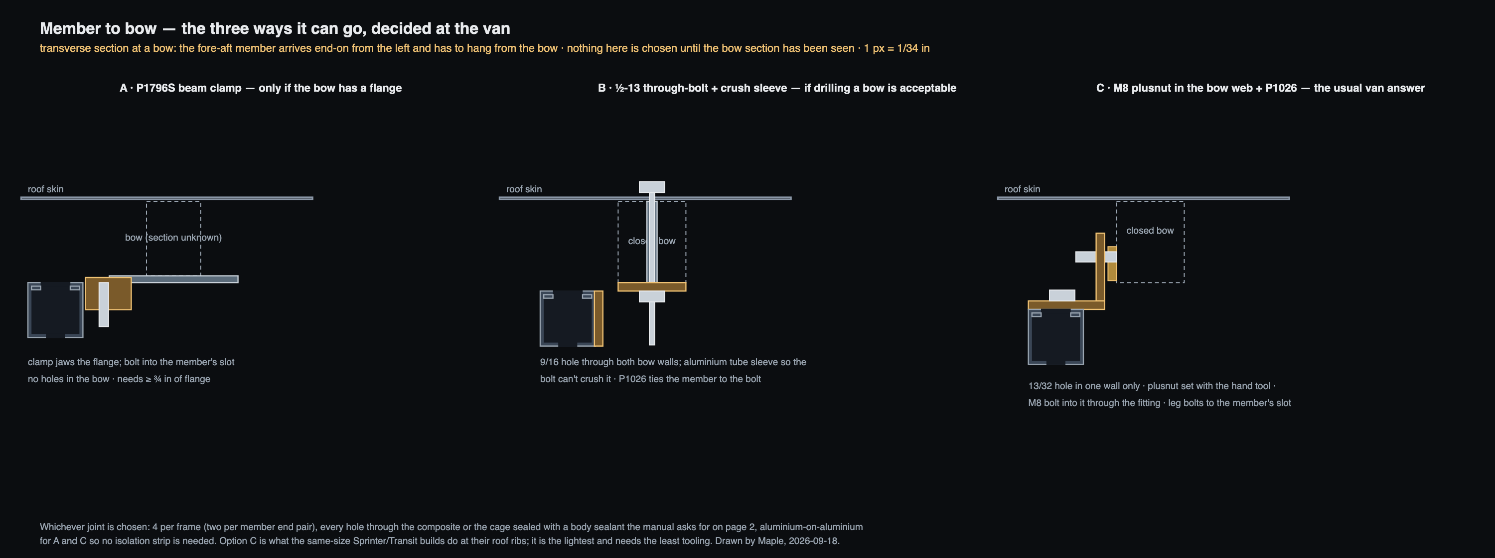
- The one rule that follows. Put each opening in a bay between two bows and hang the frame from those bows. Never cut, notch or drill through a bow's load-carrying flanges; if a bow has to be drilled at all (option B below), it is one clean hole through the web with a sleeve, and the answer is "not until the bow section has been seen".
2 · What each appliance demands — from its own manual
the frame exists to meet these lines · both manuals were downloaded and read on 2026-09-18
Velit 3000R manual v.2024 · 75 lb · body 35.8 × 35.4 × 7 in · air-distribution box 20 × 19.7 × 2 in inside
- Opening 14¼ × 14¼ in, slope under 15°, and 3 in of clear interior trim around the opening edges (§3–4). The 3 in is why the headers sit 1½ in off the opening and the flat bar ring is 2 in wide: the interior bracket and ADB frame need that room.
- Gasket over the opening, then "support foam blocks around the perimeter of the AC unit" (§6–7). That second line is the whole reason for the outboard members: the unit's edges bear on foam blocks 35 in apart, far outside the 14¼ hole, and the composite skin cannot carry that alone.
- Four M8 threaded rods drop from the unit through the roof; the mounting bracket goes "against the inner side of the roof opening" and the rods pass through its four holes; nuts torqued to 3.3–4.2 lb·ft (§10–14). So the bracket clamps the roof stack — skin + whatever is under it — against the unit's gasket. The stack is what our ring and headers become.
- Not published: the rod length, so the maximum stack thickness. Measure the supplied rods before cutting anything; if 1.6 mm skin + ¼ in bar leaves too little thread, the bracket sits on the bar ring alone and the strut headers stay outboard of it — the drawing already keeps them 1½ in off the opening for exactly this reason.
MaxxFan Deluxe US installation sheet 11E90001K · 14 × 14 in opening
- Roof thickness 1⅛ to 6½ in; below 1⅛ "build additional thickness at the ceiling opening using wood or other suitable material". A bare 1.6 mm composite skin is far under the minimum — the fan's frame is not optional, and the ¼ in ring plus 1⅝ in strut lands at 1.9 in, inside the range.
- The roof receiving flange screws to the roof, then the fan drops onto the flange and is held with four ¾ in #10 screws. The flange screws want to bite something — the flat-bar ring is what they bite.
- Sealant compatible with the plastic flange only — no petroleum-based sealants, no polysulfide; the sheet names a non-acetic silicone. Keep the roof-rack EPDM and the frame's sealant off the flange.
- 8 in clear behind the flange for the lid to open. That sets where the fan reserve sits relative to crossbar C4 on the rack plan.
3 · The design, in three drawings
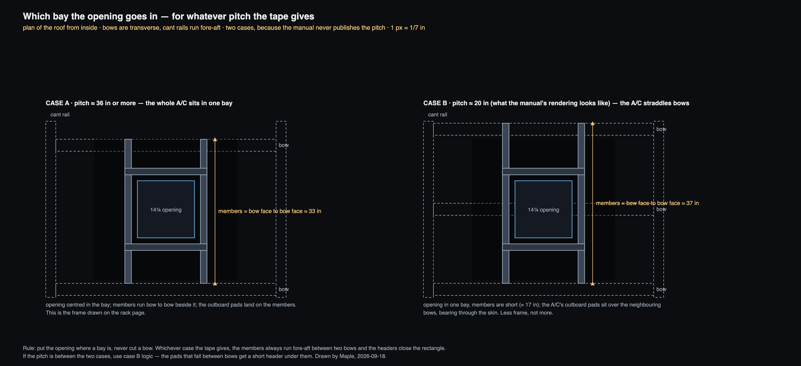
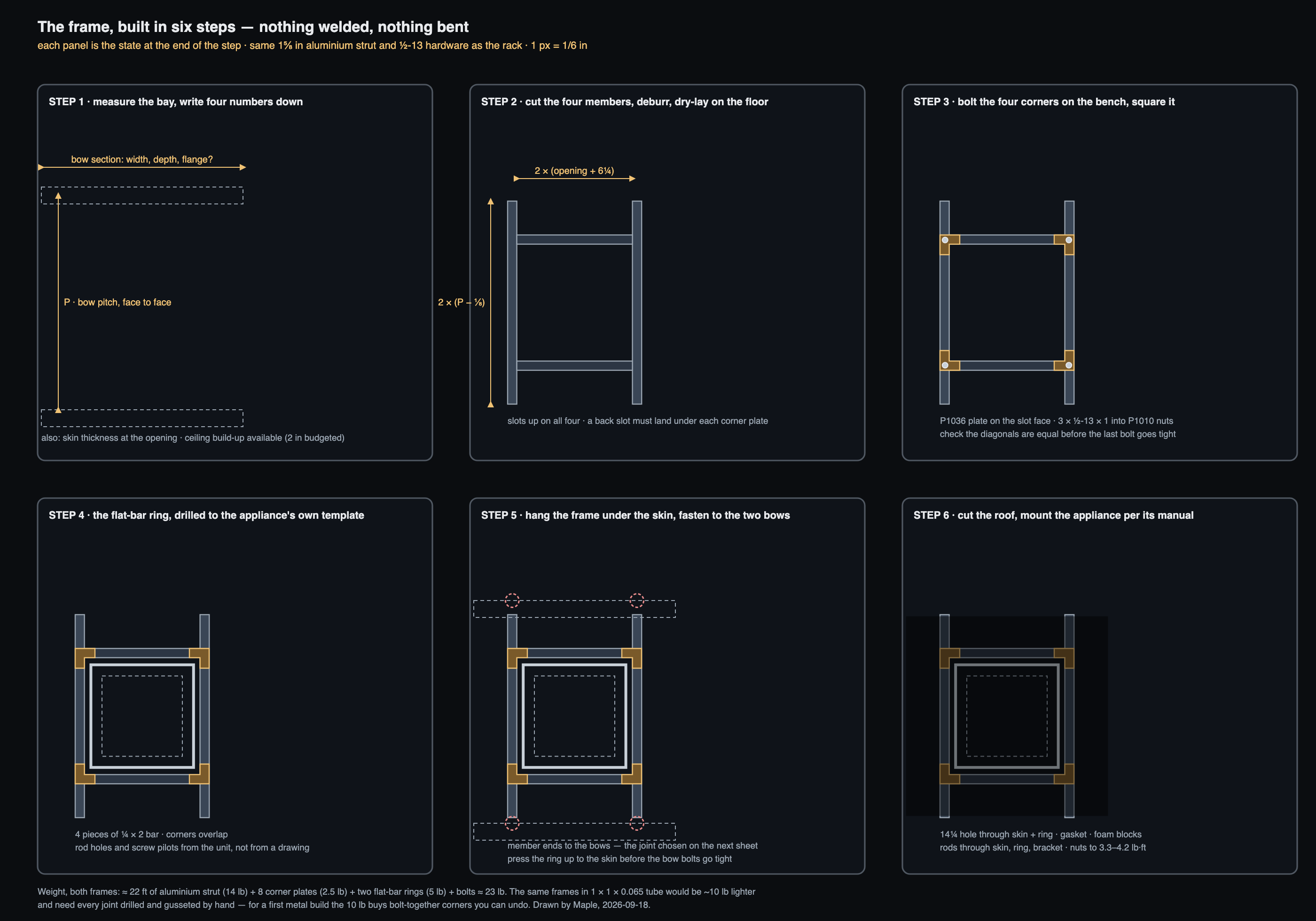
plan and section on the rack page · here: which bay, the six build states, and the one joint still open
4 · What to buy — both frames, one order with the rack
line numbers continue the rack page's list (22–27) · lengths are formulas of the measured pitch P and the opening O · example column uses P = 20, O = 14¼
| # | Part | Qty | Cut / size rule | Example | Notes |
|---|---|---|---|---|---|
| Members — Unistrut P1000T, aluminium, 1⅝ × 1⅝ in, slotted back (same stick as the rack; ~22 ft total for both frames) | |||||
| 22 | Fore-aft members | 4 | P − ⅛ in (bow face to bow face, minus a saw kerf of play) | 19⅞ in | Two per frame. Cut so a back slot lands where each corner plate goes. |
| 23 | Headers | 4 | O + 2 × 1½ + 2 × 1⅝ − 2 × 1⅝ = O + 3 (between the members) | 17¼ in | Two per frame, framing the opening 1½ in off its edges for the Velit's 3 in trim clearance. |
| Corners | |||||
| 24 | Unistrut P1036 3-hole flat corner plate | 8 | 3½ × 3½ in, ⅜ in thick | — | One per in-plane corner, on the slot faces. EG steel as stocked; ask for aluminium on the same call as the channel. |
| 25 | P1010 ½-13 spring nuts + ½-13 × 1 in hex bolts + flat washers | 24 + 24 + 24 | Three per plate | — | Add to the rack's line 7/8 order. |
| The ring the appliance bears on | |||||
| 26 | 6061-T6 aluminium flat bar, ¼ × 2 in | 8 pieces | 2 × (O + 4) and 2 × O per frame, lap-jointed at the corners | 2 × 18¼ + 2 × 14¼ per frame | ~13 ft total, metal supplier, ~$60. Drilled on the bench to the appliance's own template — the four M8 rod holes for the Velit, the flange screw pilots for the fan. |
| 26a | ¼-20 × ¾ in button heads + P1010-style ¼-20 spring nuts (P1008) | 8 + 8 | Two per bar piece, down into the header / member slots | — | Holds the ring to the frame before the roof is cut; the appliance's own hardware does the real clamping afterwards. |
| Bow attachment — one of the three, decided at the van (4 joints per frame) | |||||
| 27A | Unistrut P1796S window beam clamp | 8 | Flange up to ⅞ in | — | Only if the bow has a flange. Bolts into the member's slot with a P1010. |
| 27B | ½-13 × 3½ in bolt, nyloc nut, 2 washers, aluminium crush sleeve ½ ID × ⅝ OD cut to the bow depth, + P1026 | 8 sets | 9/16 in hole through both bow walls | — | Only if inspection says a bow may be drilled through. Strongest; most invasive. |
| 27C | M8 × 1.25 plusnut (Sherex / Bollhoff style, 0.5–3 mm grip) + M8 × 20 button head + P1026 + P1010 for the member end | 8 sets | 13/32 in hole, one bow wall | — | Default. Needs the plusnut hand tool (~$40). The P1026's other leg bolts into the member's slot. |
| Sealing, isolation, consumables | |||||
| 28 | Body sealant for every hole in the composite or the cage (Sikaflex 221 or equivalent polyurethane) | 1 tube | — | — | The manual's page-2 rule. Not on the MaxxFan flange — that gets the non-acetic silicone its sheet names. |
| 29 | EPDM strip 1/16 × 1½ in (rack line 18) | from the rack roll | — | — | Under any steel plate on aluminium channel; unnecessary if the P1036s come in aluminium. |
| 30 | Velit's own rods, bracket, gasket, foam blocks · MaxxFan's own flange, screws, garnish ring | supplied | — | — | Never substituted, never torqued to a rack figure. |
Weight. 22 ft of aluminium P1000T ≈ 14 lb · eight P1036 ≈ 2.5 lb (steel; ~1 lb in aluminium) · ~13 ft of ¼ × 2 bar ≈ 5 lb · bolts, nuts, fittings ≈ 2 lb. ≈ 23 lb for both frames. The Velit on top adds 75 lb, the fan ~10 lb.
Price, as displayed on 2026-09-16/18. P1036 ~$4 ea, P1026 $2.20 ea, P1796S ~$8 ea, nuts and bolts a few dollars a bag, flat bar ~$60, plusnut tool ~$40 — everything except the channel comes to roughly $150. The channel is in the rack quote.
5 · Tools — what a first-timer actually needs
- Cutting aluminium strut: a mitre saw with a non-ferrous (aluminium) blade is the clean way — the cuts are square and it takes seconds. A hacksaw in a mitre box works and is quieter; expect to file the ends square. No angle grinder — it melts and grabs aluminium.
- Deburring: a flat file and a deburring tool. Every cut end, every drilled hole. Aluminium burrs are sharp and they stop parts sitting flat.
- Drilling: cordless drill, a step bit for the 13/32 and 9/16 holes, a centre punch so the bit does not walk, cutting fluid (WD-40 is fine on aluminium). Drill the flat bar on a bench with the appliance's template taped to it, never in place.
- Fastening: ¾ in socket (½-13 hex bolts), 13 mm socket (M8), a small torque wrench that reads down to 3 lb·ft for the Velit rods, a ¼ in drive ratchet for the ¼-20s. Strut nuts turn under the lips with a finger; the bolt pulls them up.
- Squaring: a framing square, a tape, and the diagonal check — a rectangle is square when both diagonals measure the same.
- Option C only: a plusnut / rivnut hand tool with an M8 mandrel.
- Roof cut: jigsaw with a fine metal blade, or an oscillating multi-tool, for the 1.6 mm composite and the ¼ in bar underneath it. Tape the line, drill a start hole in each corner, cut from outside.
6 · The build, step by step
bench first, roof last · each step ends with a check you can see
- Measure and photograph the bay. From inside, with the headliner out: bow pitch face to face at both ends of the bay (they may differ), bow section — width, depth, whether there is a flange and how wide, open or closed profile — skin thickness at a drilled ¼ in pilot near the planned opening, and the depth from the skin to the finished ceiling line. Write the four numbers on the drawing. Decide case A or case B from the pitch, and joint A, B or C from the section.
- Mark the opening on the roof from outside. Centre it in the bay in both directions, keeping 3 in of trim clearance inside and — for the fan — 8 in clear behind the flange. Confirm from inside that no bow, stringer or wire runs through the square. Do not cut yet. Tape the outline.
- Cut the eight strut members to the rule in the table, deburr, and dry-lay both frames on the floor slots-up. Check that a back slot falls under every corner plate and every bar bolt; if one does not, shift the cut by up to 1 in rather than drilling. Lines 22, 23.
- Bolt the corners on the bench. P1036 on the slot face, three ½-13 × 1 in bolts each into P1010 nuts dropped in the slots — nut in, quarter turn so it seats under the lips, bolt through the plate into it, snug. Square the frame by diagonals, then tighten in a circle. Lines 24, 25. EPDM under steel plates.
- Make the flat-bar ring. Cut the four bars, lap the corners, clamp the ring to the frame and drill the ¼-20 holes through bar and slot. Then tape the appliance's own template to the ring and drill the rod holes (Velit) or screw pilots (fan). Line 26, 26a. This is the only "fabricated" piece, and it is four straight cuts and some holes.
- Fit the bow hardware to the frame first. Joint C: bolt a P1026 to each member end through its slot, leg pointing up, so the frame arrives with its brackets on. Joint A: beam clamps loose on the member ends. Joint B: nothing on the frame yet. Line 27.
- Offer the frame up. Two people or a couple of props. Press the ring flat to the underside of the skin, centred on the taped outline, and mark the bow holes through the P1026 holes (C) or the bow flange positions (A). Take it down.
- Make the bow joints. Joint C: centre-punch, drill 13/32 in through one wall only, deburr, set the plusnut with the hand tool, a dab of sealant in the hole first. Joint A: nothing to drill. Joint B: only with the bow section in hand and inspection's yes. Every hole sealed — manual page 2.
- Hang it. Frame up, bolts in finger-tight, ring pressed to the skin, then tighten the bow bolts, then re-check the corner bolts. Push up on the ring: nothing should move. Now the frame is part of the van.
- Cut the roof. From outside, on the taped line, corner start holes, jigsaw through skin and bar together so the two edges match. Deburr, vacuum the swarf, seal the cut edge. 14¼ in for the Velit, 14 in for the fan, per each manual.
- Mount the appliance exactly per its manual. Velit: gasket, foam blocks, rods, bracket inside against the ring, nuts to 3.3–4.2 lb·ft, ADB frame to the bracket. Fan: receiving flange sealed and screwed to the ring, fan onto the flange, four #10 screws, garnish ring trimmed to the 1.9 in stack. Line 30. Nothing substituted.
- Leak test, then load test. Hose on the roof for ten minutes, inspect inside. Then a hundred loaded miles, and re-check every bolt on the frame and the appliance. Same rule as the rack's stage 5.
Status: a bolt-together design in the rack's parts family, written for a first build, with cut rules as formulas of the four measurements the van has to give. Sits under the appliance page (why) and beside the rack page (the same order). Drawn and written by Maple, 2026-09-18.