← back to the build document · the standard brackets · building the roof rack · the roof frame · mounting the a/c & fan

Rack design history

Everything on this page is retired. It is the fabricated-parts version of the roof rack — cut base plates, gusset cheeks, pedestal posts, top saddles and pipe spacers — plus the exterior A/C and fan bays that went when the appliances moved inside. It is kept so the reasoning is traceable, not because any of it is buildable.

The current direction is catalog parts: the standard brackets and the current graphics →

Nothing on this page is a productThe gold, green and orange parts in these drawings are proposed custom pieces drawn for this project. They are not Unistrut, TNUTZ or anyone else's catalog item. Do not carry a shape off this page into a supplier conversation, and do not read any dimension, hole or spacer here as current.

The fabricated supports

retired 2026-09-16 · replaced by catalog gusseted fittings

Each support was a bolted assembly of cut parts: a base plate, a short square-tube post, L-angles, triangular gusset cheeks and a fabricated top saddle, all drilled to a hole pattern that was never worked out. A stocked gusseted fitting is that corner in one piece, which is why the assembly went.
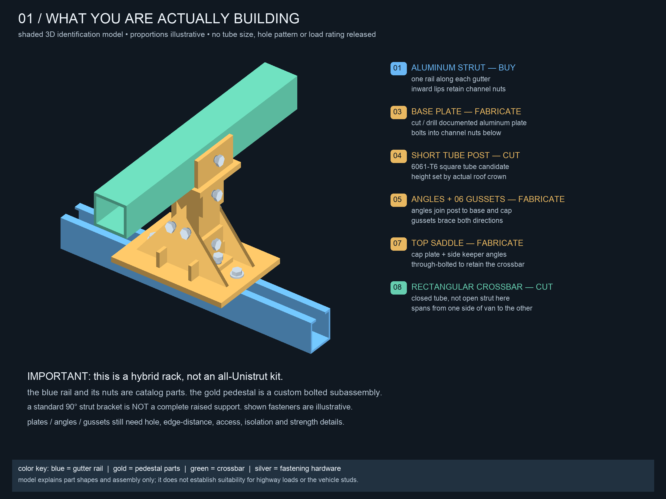
Retired concept render of one assembled custom raised support: a blue inward-lip strut rail front to back, a gold cut base plate bolted to it through channel nuts, a short gold square tube post braced by angles and triangular gusset cheeks, a gold cap plate and keeper angles on top, and a green closed rectangular crossbar tube through-bolted into the keepers.
Retired — one support as a fabricated assembly. The whole gold stack between the blue rail and the green crossbar is what a pair of catalog gusseted fittings and a cut-to-length upright now replace. Drawn by Mickey.
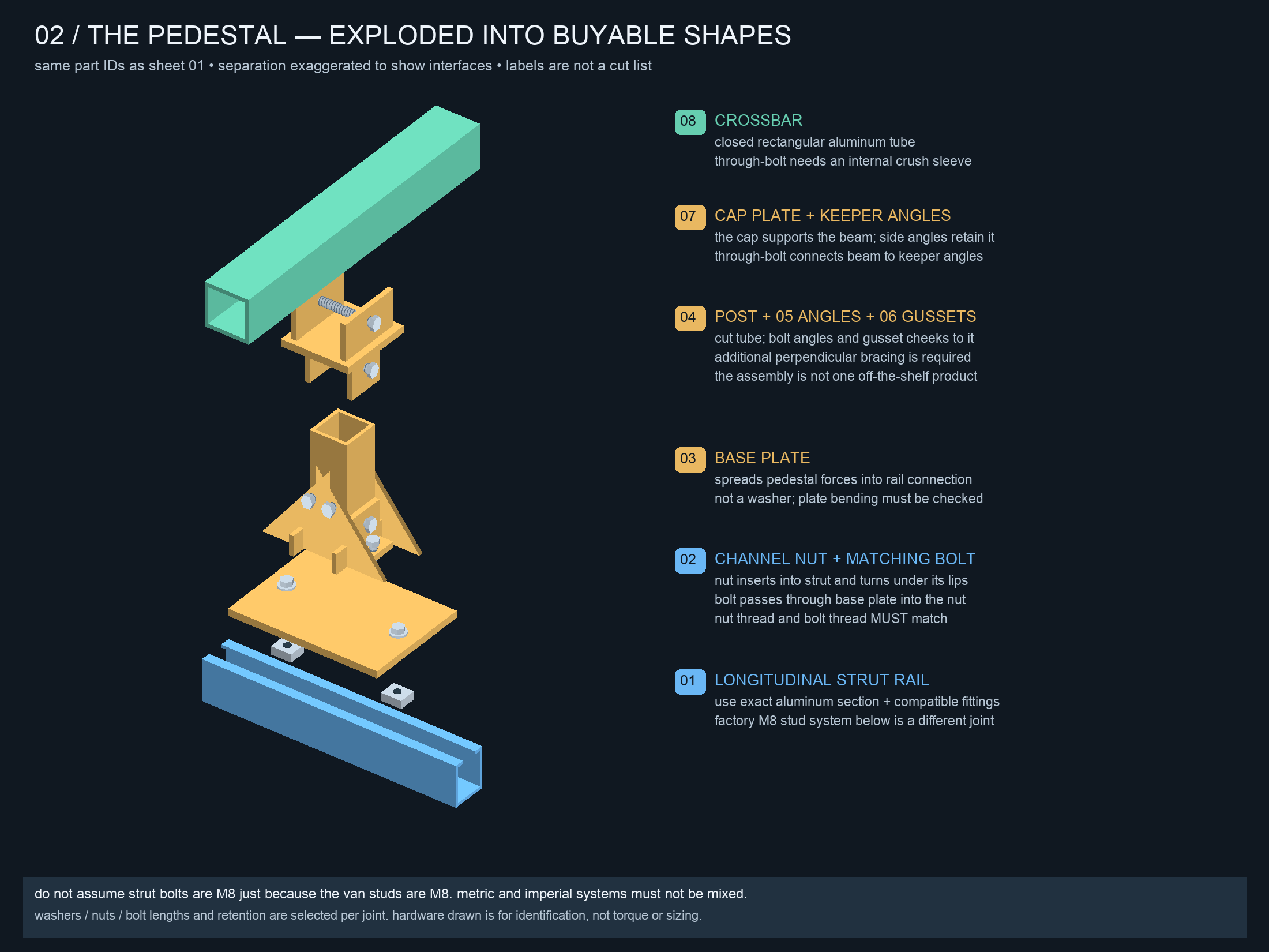
Retired exploded view of the same custom raised support, separated vertically: the blue longitudinal strut rail, channel nuts under its lips, the gold base plate, the post with angles and gussets, the cap plate and keeper angles, and the green crossbar.
Retired — the same support, exploded. A useful count of how many made-to-order pieces one corner used to need. Drawn by Mickey.
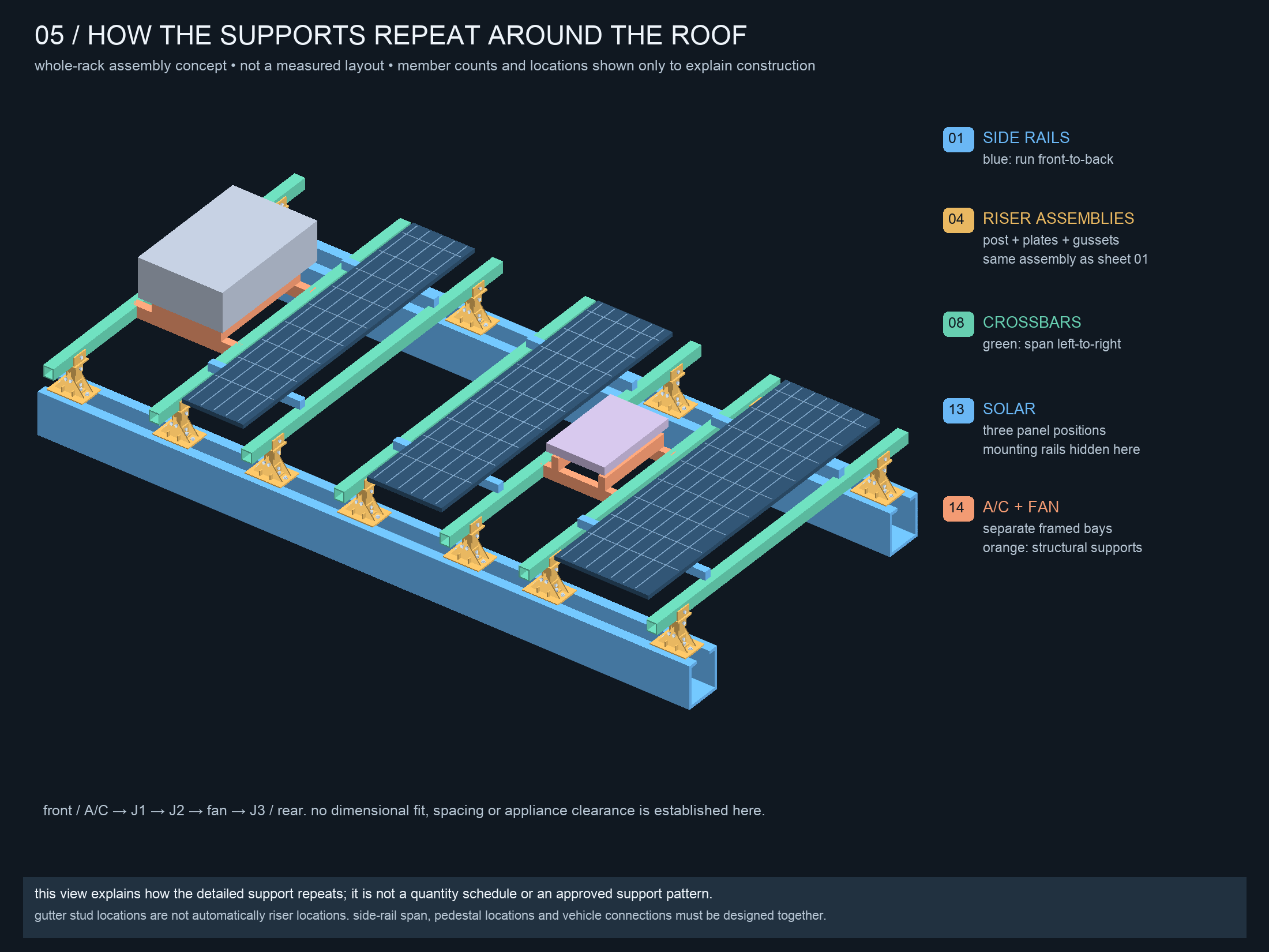
Retired shaded overview of the complete custom rack: blue side rails down both gutter lines, repeated gold custom raised supports, green crossbars over the roof crown, and orange equipment frames for the A/C and fan.
Retired — the whole rack with fabricated supports and exterior appliance bays. Two retired ideas in one drawing: the made-up supports, and appliances carried on the rack. The appliances moved to an internal frame. Drawn by Mickey.

The fabrication sequence

retired 2026-09-16 · replaced by the current build order

Until 2026-09-16 the build page carried a twenty-one step, six-phase guide for a custom rack: an aluminium strut rail on the gutter studs, cut pipe spacers at each stud, a bolted pedestal of cut plates, angles and gussets to buy roof clearance, and a cut crossbar tube captured in a fabricated saddle. Almost every part it consumed was one that had to be made. That is why the sequence went rather than being edited.
What specifically is retiredThe twenty-one numbered steps and their six phases · the four-layer gutter / rail / braced-riser / crossbar architecture as a construction instruction · the cut 1.35″ pipe sleeve and 25 mm coupling-nut stack · the bench-assembled pedestal · the fabricated top saddle · the exterior appliance bays.
What survived into the current pagesThe operating lessons, not the construction: separate clearance from ventilation · name a locking method and a torque per joint · inspect visually on a schedule · close the ram-air path at the leading edge · lift glass by the frame. Those live in the current build order.
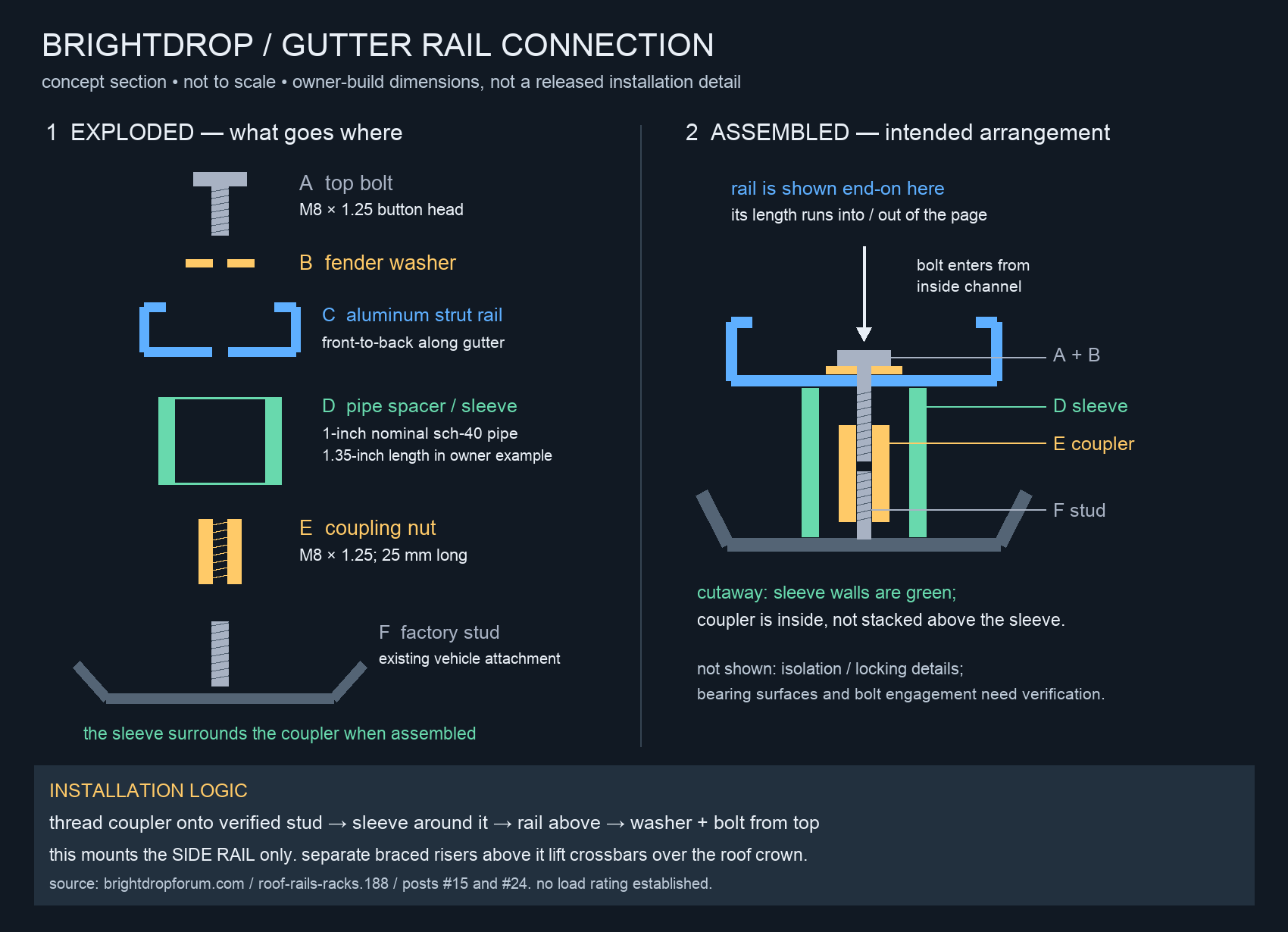
Retired concept section of a custom gutter rail connection: exploded stack of an M8 button-head bolt, fender washer, aluminium strut rail, a pipe spacer sleeve cut from 1 inch nominal schedule-40 pipe, a 25 mm M8 coupling nut and the factory stud, beside an assembled cutaway showing the coupling nut nested inside the sleeve.
Retired — the custom gutter connection. A made-up spacer stack on the factory stud. No replacement drawing exists: the vehicle attachment is an open item on the build page, and nothing has been invented to fill it. Drawn by Mickey.
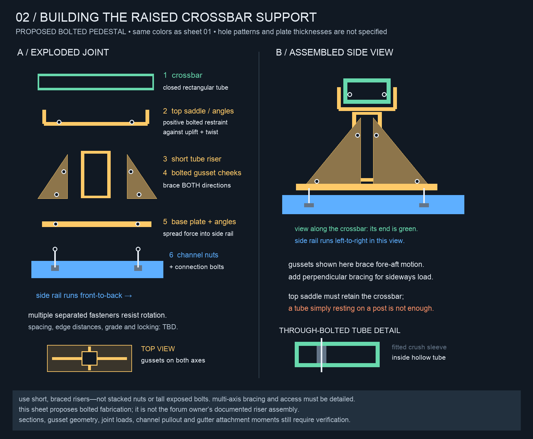
Retired concept drawing of a custom raised crossbar support: exploded joint keyed one to six with a closed rectangular crossbar tube, fabricated top saddle angles, a short tube riser with bolted triangular gusset cheeks, a cut base plate with angles, and channel nuts into the rail, beside an assembled side view with a crush sleeve inset.
Retired — the custom braced riser. Catalog gussets exist; this pedestal was the reason to believe they did not. Drawn by Mickey.
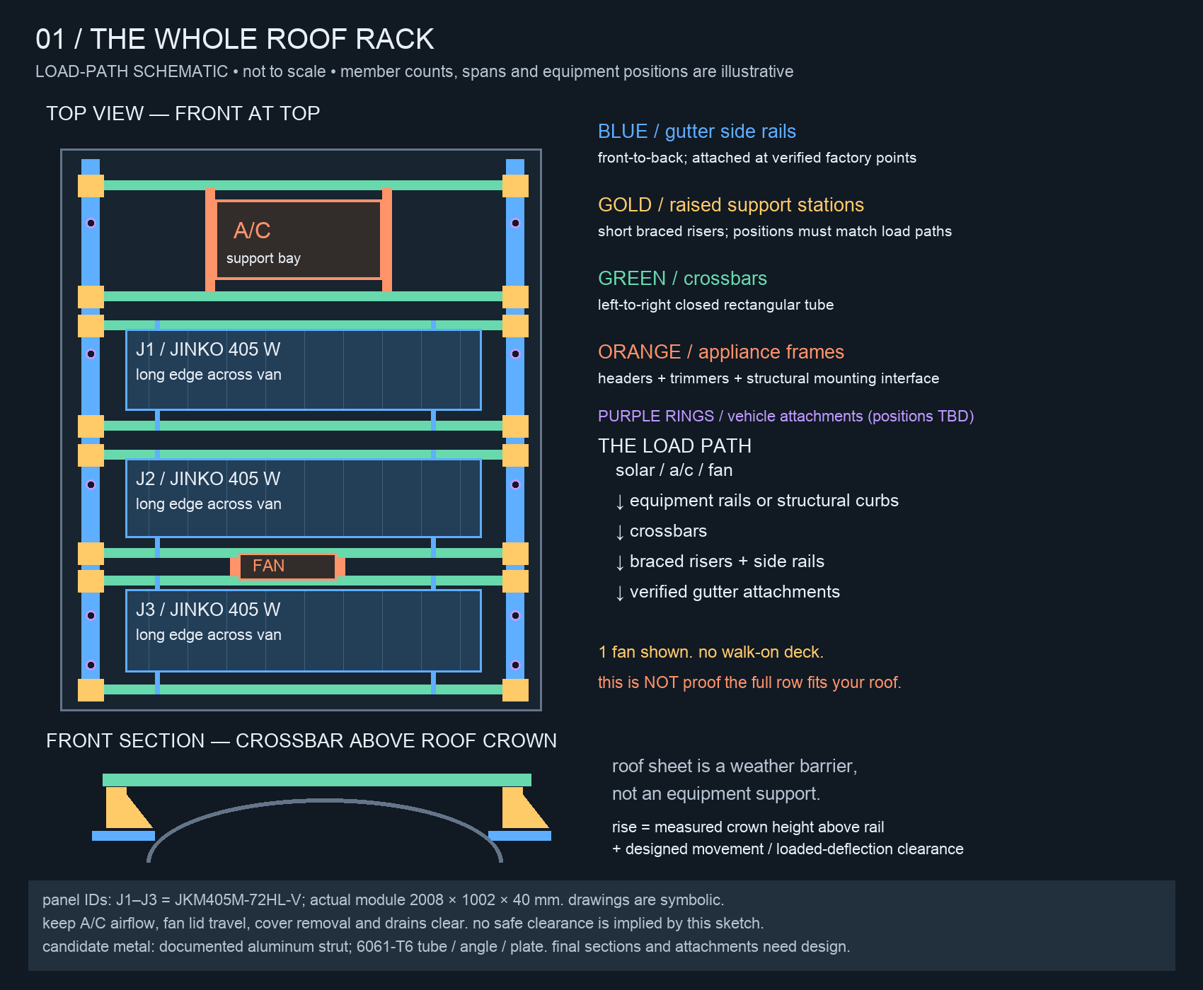
Retired load-path schematic of the custom roof rack: blue gutter side rails down both sides, gold raised support stations, green crossbars spanning left to right, orange A/C and fan bays, and three panel footprints, with a front section showing crossbars held above the crowned roof.
Retired — the whole custom rack, with exterior appliance bays. Two retired ideas in one drawing: the fabricated supports, and appliances carried on the rack. Drawn by Mickey.
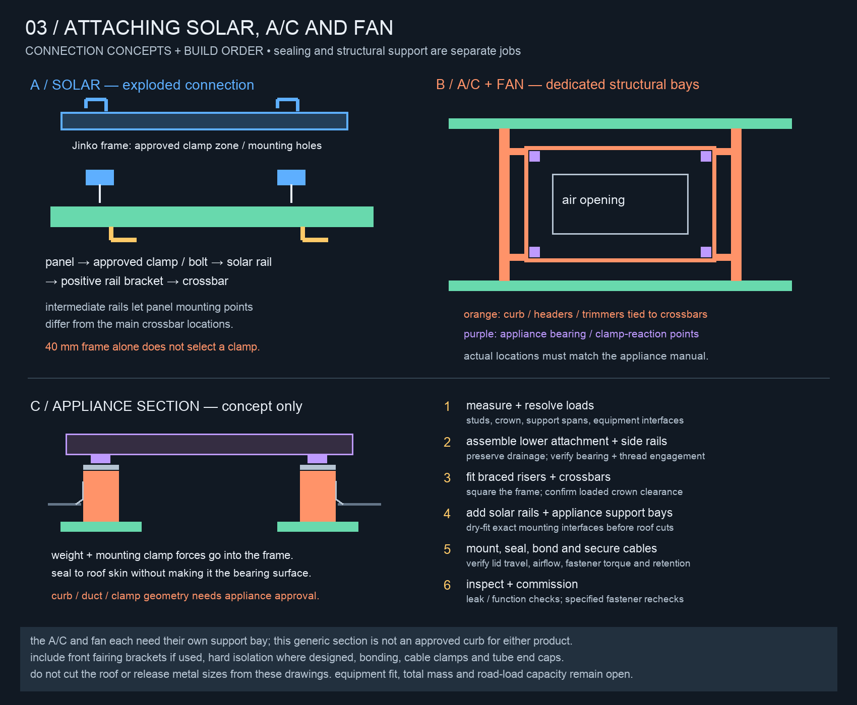
Retired three-part drawing: an exploded solar connection from Jinko frame to clamp to rail to bracket to crossbar; custom A/C and fan structural bays with curb, headers and trimmers; and an appliance section with a numbered six-step build order.
Retired — equipment connections and the old build order. Panels B and C went when the appliances moved inside; panel A's clamp-or-holes logic now lives in the current workflow as “the module manual decides.” Drawn by Mickey.

The roof frame concepts

retired 2026-09-16 · replaced by the current whole-frame graphic

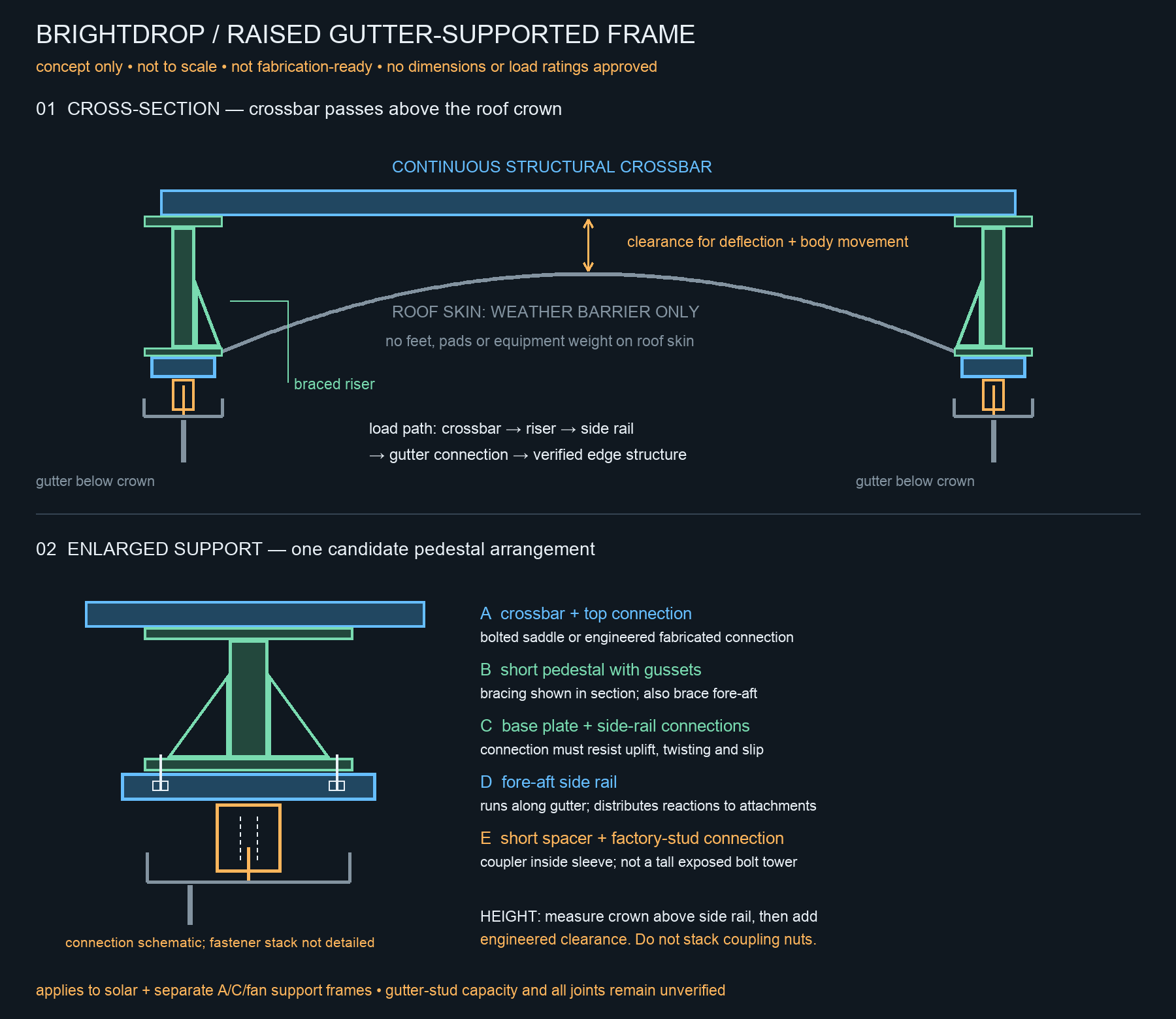
Two sheets from the roof-frame page. The first still carried structural A/C and fan curbs on the exterior frame, which moved inside. The second was the fabricated braced pedestal. The ideas that survived them — the crossbar bridges the roof crown and never touches it, the load lands at the edge, and the clearance gap is sized for deflection and body movement — are stated on the current page and do not depend on these drawings.
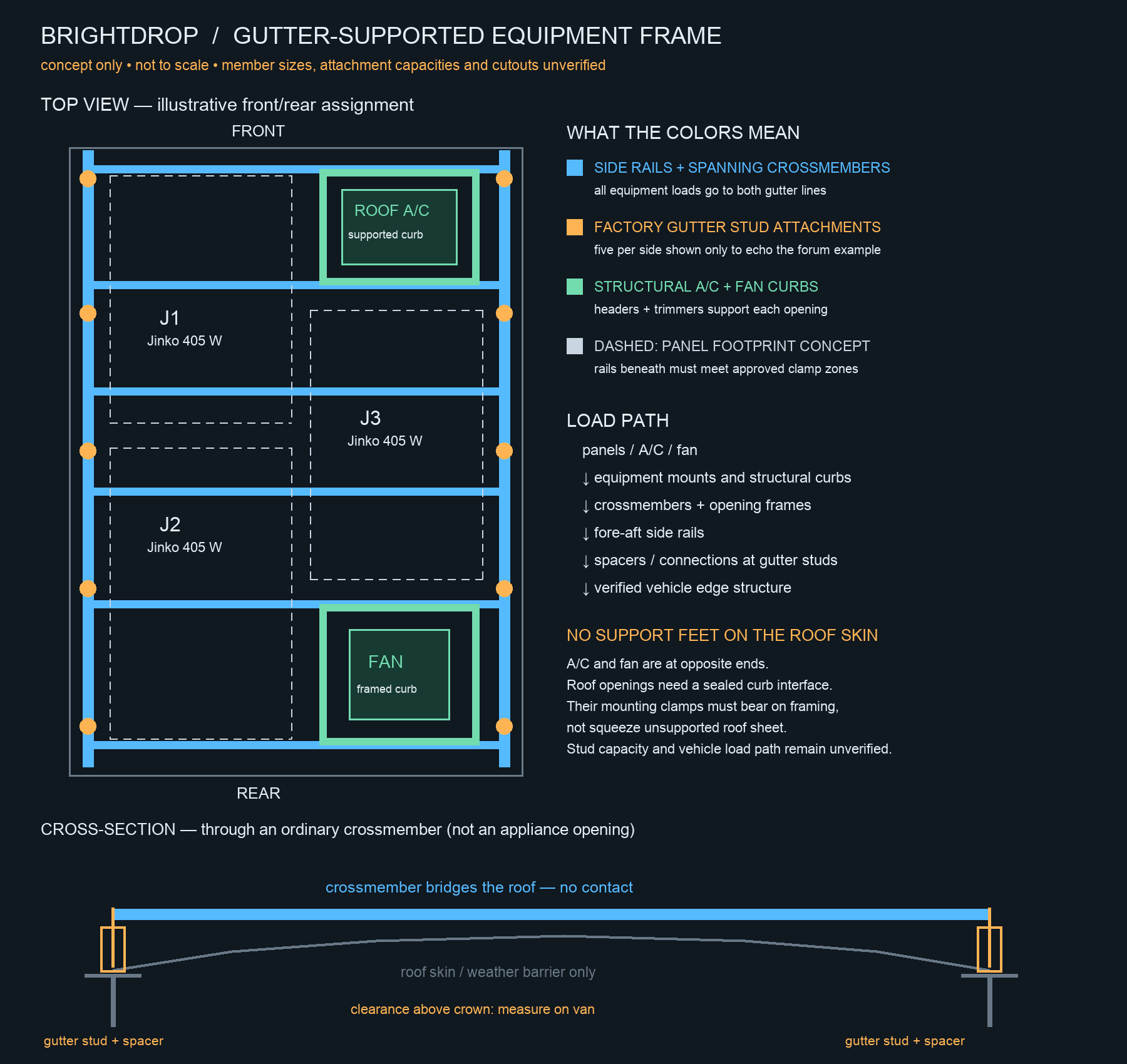
Retired concept drawing of a gutter-supported equipment frame on a BrightDrop Zevo roof: top view showing fore-aft side rails on the gutter studs, crossmembers spanning gutter line to gutter line, structural curbs for the A/C at the front and the fan at the rear, three dashed panel footprints; below it a cross-section showing the crossmember bridging over the crowned roof skin without touching it
Retired — the gutter-supported equipment frame. The green structural curbs framing A/C and fan openings went when the appliances moved inside; the fabricated members went with the catalog-parts direction. Not a product, not to scale, not a layout. Drawn by Mickey.
Retired concept drawing of a raised gutter-supported frame on a BrightDrop Zevo. Top panel is a cross-section: a continuous blue structural crossbar spans the van, held above the grey crowned roof skin by green braced risers standing on the side rails at each gutter, with the clearance gap dimensioned for deflection and body movement and the roof skin labelled weather barrier only. Bottom panel is an enlarged view of one support, keyed A to E: crossbar and top connection, short gusseted pedestal, base plate and side-rail connections, fore-aft side rail, and a short orange spacer at the factory stud drawn schematically without the fastener stack.
Retired — the fabricated braced-riser concept. Green: a custom pedestal and base plate. Orange: a cut spacer at the factory stud. Neither is a part any more. Riser height, connections and attachment capacity were unverified here and still are. Drawn by Mickey.

The old illustrated hardware guide

The earlier download belonged to the fabrication packet: the superseded fabrication guide (PDF, historical) →. It documents the made-up parts, not the catalog fittings.

The current download is the three-page catalog packet on the standard-brackets page. The official P2484 cut sheet (PDF) is a supplier document and stays current.