← back to the build document · the rack for the lengthwise layout · the build order · the roof frame · the two joints · the cut pattern · what to buy · making it · what to measure first
The front fairing
The rack lifts the panels about 10 in off the roof, and at highway speed that gap is a scoop. The fairing is one flat aluminium plate across the front of the rack, leaning back, that closes the scoop at the leading edge and leaves the sides and rear open. This page is the plate drawn to scale, the two joints that hold it, the shape to cut, and the parts to buy.
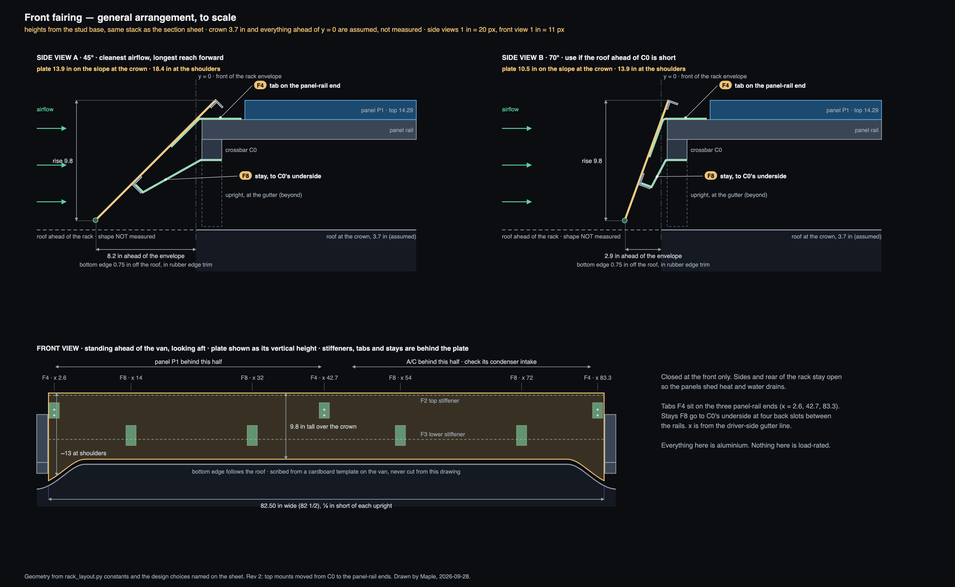
What it looks like, to scale
two side views at the van centreline and one front view · heights from the stud base, same stack as the rack section
The two joints
side views at a panel rail and at a stay, both angles · every part numbered F1–F9, matching the table below
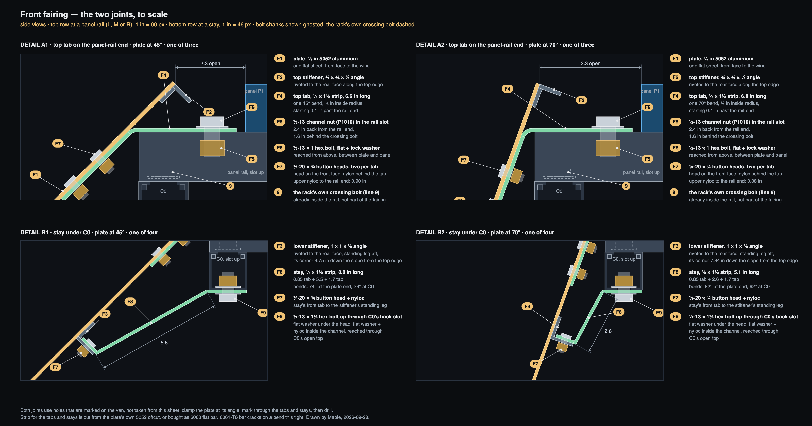
- The tab's channel nut sits 2.4 in back from the rail end, which is 1.6 in behind the rack's own crossing bolt inside the same rail. It is reached with a socket from above, through the slot between the plate and panel P1.
- The nyloc behind the tab's upper hole clears the rail end by 0.90 in at 45° and 0.39 in at 70°. That is why the two tab holes are 1.3 and 2.5 in down the tab's leg and no higher.
- Nothing is drilled in the rack. The tabs use the rail slots, the stays use C0's back slots. Every drilled hole is in the fairing's own parts.
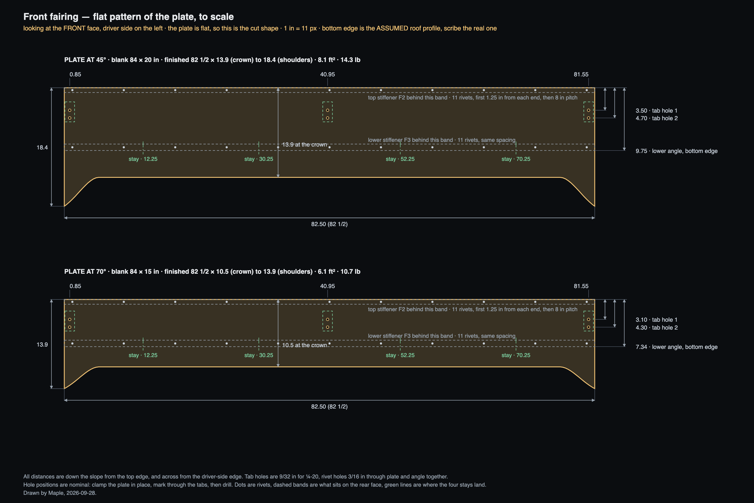
The shape to cut
flat pattern, looking at the front face, driver side on the left · the plate is flat so there is no bend allowance
What to buy
quantities for the drawings above, either angle · none of this has been priced yet
| # | Part | Qty | Where it goes | Source |
|---|---|---|---|---|
| A · Aluminium | ||||
| F1 | 5052-H32 aluminium sheet, ⅛ in (0.125) | 1 blank 84 × 20 in at 45° 84 × 15 in at 70° | The plate. A metal supplier shears the blank; otherwise it comes out of a 4 × 8 ft sheet, and the offcut makes the strip for F4 and F8 | metal supplier |
| F2 | Aluminium angle, ¾ × ¾ × ⅛ in, 6063 | 1 × 82½ in one 8 ft length | Top stiffener, on the rear face along the top edge | metal supplier or hardware store |
| F3 | Aluminium angle, 1 × 1 × ⅛ in, 6063 | 1 × 82½ in one 8 ft length | Lower stiffener, on the rear face, 9.75 in down at 45° or 7.34 in at 70°. The stays bolt to its standing leg | metal supplier or hardware store |
| F4 | Top tabs — ⅛ × 1½ in strip | 3 × 6.6 in at 45° 3 × 6.8 in at 70° | One on each panel-rail end. One bend, ¼ in inside radius | strips cut from the F1 offcut, or one 6 ft length of 6063 flat bar. Not 6061-T6 — it cracks on a bend this tight |
| F8 | Stays — ⅛ × 1½ in strip | 4 × 8.0 in at 45° 4 × 5.1 in at 70° | Lower stiffener to C0's underside, at x = 14, 32, 54 and 72 in from the driver-side gutter line, moved to the nearest back slot. Two bends each | |
| B · Fasteners — stainless | ||||
| F5 | Unistrut P1010 ½-13 channel nut with spring | 3 | In each panel rail's slot, 2.4 in back from the rail end. Same nut as rack line 7 | with the rack order |
| F6 | ½-13 × 1 in hex bolt, flat washer, lock washer | 3 | Tab to panel rail. Same bolt as rack line 8 | with the rack order |
| F7 | ¼-20 × ¾ in button-head screw, 2 flat washers, nyloc nut | 10 | Six hold the tabs to the plate, head on the front face. Four hold the stays to the lower stiffener | hardware store |
| F9 | ½-13 × 1¼ in hex bolt, 2 flat washers, nyloc nut | 4 | Stay to C0: up through C0's back slot, washer and nut inside the channel | hardware store |
| F10 | 3/16 in blind rivets, aluminium, grip range covering ¼ in | 22 a box of 50 | Eleven per stiffener, first one 1.25 in from each end, then 8 in pitch | hardware store |
| C · Edge | ||||
| F11 | Push-on EPDM edge trim for a ⅛ in edge | 8 ft | Along the bottom edge, so aluminium never touches the roof | hardware or auto-parts store |
Tools. Cardboard and a marker for the roof template, a jigsaw with a metal blade, a file, a rivet gun, a vise for the bends, and 3/16, 9/32 and 9/16 in drill bits.
Making it, in this order
after the rack is up and the panels are down — it is the last thing on the roof
- Measure the roof and pick the angle. The three numbers in the next section. Nothing gets bought before this.
- Make the roof template. Hold a strip of cardboard across the roof where the bottom edge will land — 8.2 in ahead of the rack at 45°, 2.9 in at 70° — lean it at the plate's angle, and scribe the roof curve onto it.
- Cut the plate. Top edge and both ends from the pattern, bottom edge from the template, ¾ in short of the roof. File every edge.
- Rivet the two stiffeners to the rear face. Drill plate and angle together, 3/16 in, eleven rivets each.
- Cut and bend three tabs and four stays. Bend in a vise over a ¼ in radius. Tab: one bend of 45° or 70°. Stay: 74° and 29° at 45°, 82° and 62° at 70°. Bend one stay first and offer it up before bending the other three.
- Tabs onto the rail ends, finger-tight. Channel nut in the slot, 2.4 in back from the rail end.
- Clamp the plate to the tabs with its top edge level with the top of the glass and its bottom edge ¾ in off the roof. Mark the six tab holes through the tabs, take the plate down, drill 9/32 in, bolt up.
- Stays. Bolt each stay to C0's underside at the nearest back slot, mark the stiffener's standing leg through the stay, drill, bolt.
- Edge trim on the bottom edge, then tighten everything. Check it again after the first loaded highway miles, with the rack's own re-torque.
What to measure first
three measurements on the van, and what each one moves
- Usable roof ahead of the front of the rack. Picks the angle. 45° needs 8.2 in plus room for the edge trim; 70° needs 2.9 in. It also says whether the roof is still the same shape that far forward.
- Gutter line to gutter line. The plate is that number minus 3½ in: two 1⅝ in uprights and ⅛ in each side. On the assumed 86 in it is 82.5 in. Moves F1, F2 and F3.
- Roof crown above the stud base. Assumed 3.7 in, same as the rack. Every inch of extra crown takes an inch off the plate's height over the crown. Moves F1's blank height.
Status: drawn to scale from the rack's own constants, both angles, not yet measured against the van and not load-rated. Replaces line 21 on the rack's parts list. Drawn and written by Maple, 2026-09-28.